How 30 Percent Open Area Ratio in Perforated Panels Facade Controls Solar Heat Gain
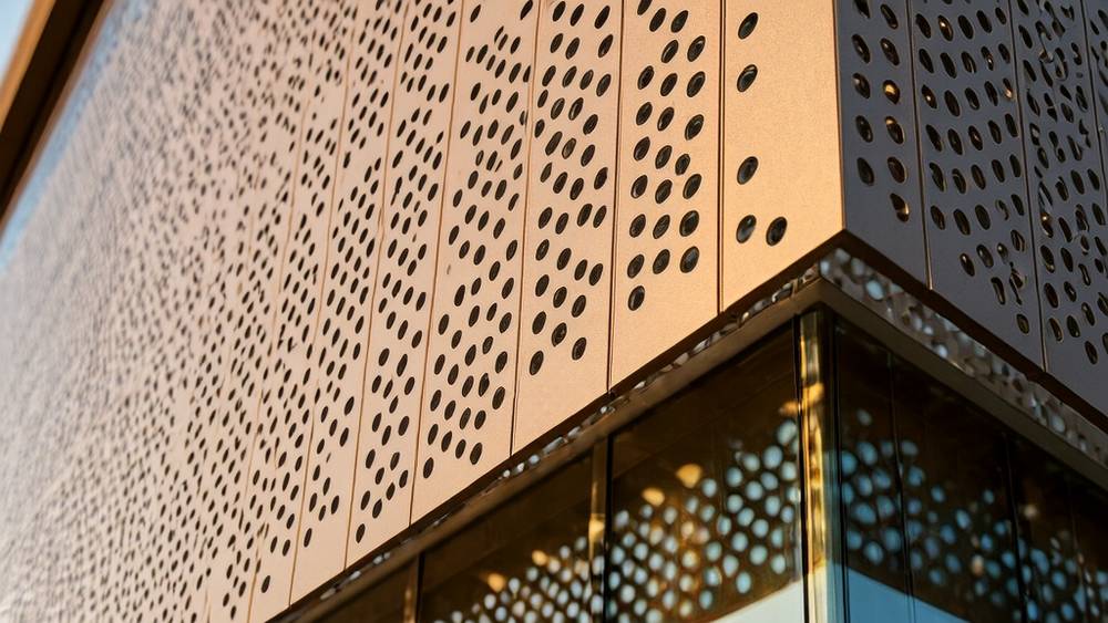
When a building envelope traps heat behind a perforated panels facade, the result is not just thermal discomfort. Excess solar gain pushes HVAC systems past their design limits, drives up energy costs, and can create internal glare that makes workspaces unusable. Architects and facade engineers specifying perforated aluminium panels often focus on aesthetics — hole diameter, pitch, pattern geometry — while underestimating how open area ratio directly governs solar heat gain coefficient for the entire double-skin assembly. This is not a secondary consideration. In projects across the Middle East, Southeast Asia, and southern Europe, the wrong open area percentage has forced costly post-occupancy retrofits: additional internal blinds, low-E film application, even full panel replacement. Getting the open area ratio right at specification stage determines whether the facade performs as a passive shading device or becomes a liability. This article examines the relationship between perforation geometry and solar control, the calculation methods that matter, and how to align aesthetic intent with thermal performance targets without compromising either.
How Open Area Ratio Translates to Solar Heat Gain
Open area ratio — the percentage of a panel face that is void rather than solid aluminium — is the single most consequential parameter linking perforated panels facade design to building energy performance. A panel with 15% open area blocks 85% of direct solar radiation at the outer skin. But the physics is more nuanced than simple blockage percentages suggest.
When sunlight strikes a perforated panel, three things happen simultaneously: a portion passes directly through the holes, a portion is reflected off the aluminium surface, and a portion is absorbed by the metal, which then re-radiates heat inward and outward. The absorbed fraction is particularly important. Solid aluminium panels with dark PVDF coatings can reach surface temperatures of 70-80°C under full sun. That heat radiates into the cavity between the perforated skin and the inner building envelope, creating a convection-driven thermal stack that can overwhelm ventilated facade assumptions.
The effective Solar Heat Gain Coefficient (SHGC) of a perforated panels facade assembly is not simply (1 - open area ratio). It must account for:
- Direct transmission through perforations — the only fraction that cleanly follows the open area percentage
- Secondary radiation from the heated aluminium substrate into the cavity
- Cavity ventilation rate — how quickly air moves behind the panels to evacuate accumulated heat
- Inner glazing SHGC — the performance of the window or curtain wall behind the perforated screen
Research published by the Lawrence Berkeley National Laboratory on exterior shading systems confirms that a perforated metal screen with 30% open area can reduce total fenestration SHGC by 40-55% compared to unshaded glazing, depending on cavity depth and ventilation. Narrower cavities (under 150 mm) without dedicated venting trap heat and degrade performance significantly.
Matching Open Area Percentages to Climate Zones
Climate dictates the starting point for open area selection. What works for a university building in Manchester will fail on a commercial tower in Dubai. The table below provides performance benchmarks drawn from project data and ASHRAE climate zone requirements.
| Climate Zone (ASHRAE) | Recommended Open Area % | Approx. Effective SHGC Reduction | Typical Cavity Depth | Example Locations |
|---|---|---|---|---|
| Zone 1-2 (Hot-Humid/Hot-Dry) | 15-25% | 55-70% | 200-400 mm | Dubai, Singapore, Phoenix |
| Zone 3 (Warm) | 25-35% | 40-55% | 150-300 mm | Athens, Sydney, Dallas |
| Zone 4 (Mixed) | 30-40% | 30-45% | 100-250 mm | Shanghai, Rome, Washington DC |
| Zone 5-6 (Cool/Cold) | 35-50% | 20-35% | 100-200 mm | London, Beijing, Chicago |
These ranges are starting points, not rigid prescriptions. A west-facing elevation in Zone 4 might need the lower end (30% open area) while the north elevation of the same building could comfortably use 45% or more. Orientation-specific calculation is essential. The perforated panels facade cannot be treated as a uniform wrap with a single specification across all elevations unless the design team accepts significant thermal performance variation.
Hole Diameter vs. Open Area: Why Pattern Geometry Matters Beyond the Percentage
Two panels can share the same 30% open area ratio but deliver different solar control performance. A panel with 5 mm holes on a tight pitch creates many small apertures; one with 20 mm holes on a wider pitch creates fewer, larger openings. The difference matters for two reasons.
First, smaller holes produce more edge diffraction of incoming light, scattering solar radiation across a wider angle rather than allowing concentrated beams through. This diffusing effect reduces glare and creates a more uniform light distribution on the inner facade. Second, smaller holes at the same open area ratio mean more solid aluminium surface area relative to hole perimeter, which increases the absorbed-and-re-radiated heat fraction.
Staggered hole patterns (60° triangular pitch) pack more holes per unit area than straight-line (square) patterns at the same spacing, yielding a higher open area ratio for a given hole diameter. The calculation for staggered pattern open area is:
Open Area % = (π × d²) / (2√3 × p²) × 100, where d = hole diameter and p = pitch (center-to-center spacing)
For square patterns, the formula simplifies to (π × d²) / (4 × p²) × 100. A 6 mm hole on 12 mm staggered pitch yields approximately 22.7% open area; the same hole and pitch in a square pattern yields 19.6%. This 3% difference may seem small, but across a 2,000 m² facade, it represents 60 m² of additional solid aluminium absorbing and re-radiating solar energy.
Coating Reflectivity and Its Interaction with Perforation
The solar reflectance of the aluminium surface — determined primarily by PVDF coating colour and formulation — compounds with open area ratio to determine total solar rejection. AAMA 2605-compliant PVDF coatings offer a Solar Reflectance Index (SRI) range from roughly 25 (dark colours) to over 90 (bright white and specialised cool pigments).
A perforated panels facade with 35% open area and a bright white PVDF coating (SRI ≈ 85) will reject a far higher fraction of incident solar energy than the same panel geometry in charcoal grey (SRI ≈ 30), because the solid portion reflects rather than absorbs. This interaction is multiplicative, not additive. The effective solar rejection can be approximated as:
Total Solar Rejection ≈ Open Area % + (Solid Area % × Solar Reflectance)
Using this simplified model: a 35% open area panel with 70% solar reflectance yields roughly 35% + (65% × 0.70) = 80.5% total solar rejection. The same panel with 25% reflectance drops to 35% + (65% × 0.25) = 51.25%. The coating choice nearly halves the facade's solar control capability.
This has practical implications for specification. When an architect specifies a dark-coloured perforated panels facade for aesthetic reasons, the facade engineer should calculate the compensatory open area increase needed to maintain thermal performance targets. In many cases, a 5-10% increase in open area ratio can offset the reduced reflectance of a darker coating — but this must be verified through thermal modelling, not guesswork.
Cavity Ventilation: The Multiplier Effect
Even the most carefully specified open area ratio underperforms if the cavity behind the panels is poorly ventilated. The cavity between perforated cladding and the inner building envelope functions as a thermal buffer zone. When air moves freely through this cavity, it carries away heat absorbed and re-radiated by the aluminium panels. When it stagnates, temperatures can climb 15-25°C above ambient.
Ventilation effectiveness depends on:
- Cavity depth: Deeper cavities (200 mm+) allow better air movement than tight cavities (under 100 mm)
- Inlet and outlet sizing: Open joints at the base and top of the facade, or dedicated louvred vents, sized at minimum 50 cm² per linear metre of facade width
- Internal obstructions: Support steel, insulation layers, and horizontal framing members that block vertical airflow
- Stack height: Taller uninterrupted cavities generate stronger natural convection
Projects exceeding 15 metres in uninterrupted facade height should consider compartmentalising the cavity with horizontal fire barriers that also function as ventilation breaks, preventing excessive stack-driven air velocities that can generate noise and pull debris into the cavity. This compartmentalisation must be coordinated with the perforated panels facade support system during shop drawing development, not added as an afterthought.
When Perforation Becomes the Primary Shading Strategy
On projects where the perforated panels facade serves as the primary — or sole — solar shading device for extensive glazing, the specification process must move beyond rules of thumb. Building energy modelling (BEM) using tools such as EnergyPlus, IES VE, or DesignBuilder becomes necessary to validate open area selection against actual annual energy performance.
The modelling should account for:
- Hourly solar angles across all 8,760 hours of a typical meteorological year
- Direct and diffuse radiation components (perforated panels handle direct radiation well; diffuse radiation passes through more readily)
- Seasonal variation — fixed perforated panels facade geometry that works brilliantly in July may block desirable solar gain in January in heating-dominated climates
- Internal load schedules — an office with high internal gains may want more shading year-round than a residential building in the same climate
For projects where full BEM is not in scope, at minimum, a single-zone shoebox model comparing 3-4 open area scenarios can prevent the most expensive specification errors. The cost of this analysis — typically £1,500-£4,000 — is trivial compared to the retrofit cost of replacing or modifying a poorly specified perforated panels facade.
Fabrication Tolerances and Their Impact on Thermal Performance
Specifying 30% open area on a drawing is one thing; receiving panels that actually deliver 30% open area is another. Perforation processes — CNC punching, turret punching, or laser cutting — each carry different tolerance ranges. CNC turret punching, the most common method for architectural perforated aluminium panels, typically holds ±0.1 mm on hole diameter and ±0.3 mm on pitch.
These tolerances may seem negligible, but they compound across a panel. A specified 6.0 mm hole at 11.0 mm staggered pitch delivers 26.9% open area. If holes come in at 5.8 mm (within a ±0.2 mm tolerance band), open area drops to 25.1% — a 1.8 percentage point reduction. Across 1,000 m² of facade, that represents an unintended 18 m² of additional solid aluminium absorbing solar radiation.
Quality assurance protocols should include:
- Statistical sampling of hole diameters using calibrated pin gauges or optical measurement, with a minimum of 5% of panels inspected
- Pitch verification using coordinate measuring templates, particularly on large-format panels exceeding 2.4 m in any dimension
- Open area verification by weight comparison — a fully perforated panel of known dimensions and alloy (typically 3003-H14 or 5052-H32 at 2.0-3.0 mm gauge) has a calculated theoretical weight; deviation from this weight directly indicates open area deviation
Suppliers like Futeng®, who operate dedicated aluminium cladding production lines with in-house CNC punching capability, typically provide mill test certificates and dimensional conformance reports as standard documentation. Requesting open area conformance data at the submittal stage, rather than assuming it, is a prudent step for any project where solar control performance is contractually specified.
Integrating Perforated Panels with Building Envelope Commissioning
Building envelope commissioning (BECx), increasingly required under ASHRAE Guideline 0 and mandated by many green building certification schemes, provides a framework for verifying that the installed perforated panels facade performs as specified. Key commissioning checks specific to perforated systems include:
- Open area spot verification on installed panels using optical methods — not every panel, but a statistically valid sample stratified by elevation and floor level
- Cavity temperature monitoring during peak solar conditions — a simple data-logging exercise that can reveal ventilation failures before they become chronic problems
- Thermal imaging of the facade under operational conditions to identify hot spots indicating blocked cavities, missing insulation, or thermal bridging at support connections
- Coating reflectance verification against specified SRI values using portable spectrophotometer measurements on installed panels
These checks matter because the perforated panels facade is fundamentally a performance specification. Unlike a solid rainscreen where the primary function is weather separation, a perforated system's value lies in its calibrated balance of openness and solidity. That calibration must be verified in the as-built condition, not just assumed from the design calculations.
Cost Implications of Solar-Optimised Perforation Specifications
Open area ratio directly affects material cost, fabrication time, and structural requirements. Higher open area means more punching operations per panel, longer machine time, and higher tooling wear — but less aluminium by weight. The cost curve is not linear.
For a typical 2.5 mm thick 3003-H14 aluminium panel with PVDF coating, fabrication costs relative to open area ratio follow this approximate pattern:
- 10-20% open area: Baseline cost. Fewer holes, faster punching cycles. Suitable for high-shading, hot-climate applications
- 20-35% open area: Moderate cost premium (5-12%). This is the most commonly specified range and represents the sweet spot where most CNC punching lines operate efficiently
- 35-50% open area: Higher cost premium (12-25%). More punching time, increased tooling wear, greater risk of panel distortion requiring post-punch flattening
- Above 50% open area: Significant cost premium (25%+). Panel structural integrity becomes a concern; increased material gauge may be required, and some patterns approach expanded mesh territory where alternative fabrication methods may be more economical
The structural implication is often overlooked: as open area increases, the remaining aluminium web between holes narrows, reducing panel stiffness. A panel with 45% open area may require an increase from 2.5 mm to 3.0 mm gauge, or the addition of stiffener ribs on the rear face, to meet wind load deflection limits under ASTM E330 or EN 13830. This adds both material cost and fabrication complexity. The solar performance gain from higher open area must be weighed against these structural and cost consequences.
For procurement managers, the key takeaway is this: specifying open area ratio without understanding its cost drivers leads to budget surprises at the tender stage. Early engagement with a perforated panels facade supplier — ideally during concept design or schematic design — allows the design team to explore open area options with real cost feedback, rather than locking in a percentage that proves unaffordable when bids arrive.
Practical Specification Checklist for Solar-Control Perforated Facades
Bringing the preceding analysis together, the following checklist provides a structured approach for architects and facade engineers developing a perforated panels facade specification where solar control is a primary performance requirement:
- Define climate zone and orientation-specific SHGC targets before selecting any aesthetic parameters. The performance requirement drives the geometry, not the reverse
- Select coating colour and SRI in parallel with open area ratio. Treat these as linked variables in a single solar control system, not as independent aesthetic and technical choices
- Specify cavity depth and ventilation openings explicitly on architectural drawings. Do not leave cavity ventilation to the contractor's discretion
- Include open area tolerance bands in the specification: e.g., "Open area ratio 30% ±2% as verified by weight comparison method"
- Require thermal performance submittals: at minimum, a calculation of effective SHGC for the complete assembly, signed by a qualified facade engineer
- Budget for BECx verification of installed open area and cavity ventilation performance
- Engage the panel fabricator early to validate that the specified pattern is manufacturable at the required tolerance and within budget
The perforated panels facade occupies a unique position in building envelope design: it is simultaneously an aesthetic statement, a solar control device, a ventilation screen, and a structural element. Getting the thermal performance right requires treating it as an engineered system rather than a decorative skin. The open area ratio is the master variable that connects all these functions. Specify it with the same rigour applied to glazing U-values and wall R-values, and the facade will deliver on its promises — reduced cooling loads, glare control, and a distinctive architectural identity that performs as well as it looks.