Custom Perforated Metal Open Area Why 23 Percent and 40 Percent Change Everything
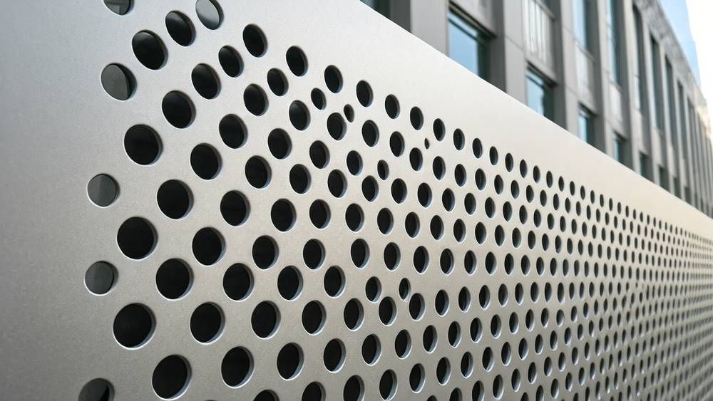
Specifying custom perforated metal for architectural projects appears straightforward on paper until the shop drawings arrive and the open area percentage you requested doesn't match the visual sample you approved six months earlier. The reason is almost always the same: someone confused gross open area with net open area, or nobody bothered to calculate either one before the CNC punches hit the sheet. This single parameter dictates airflow rates, acoustical performance, weight reduction, structural stiffness, and whether the finished facade reads as transparent or opaque from 30 metres away. Getting it wrong means panels that whistle in crosswinds, fall outside acoustic spec, or look nothing like the render. This article walks through what open area actually means for custom perforated metal, how to specify it correctly across aluminium, steel, and stainless steel grades, and where the numbers break down when bar width tolerances go unaccounted.
What Open Area Means in Custom Perforated Metal
Open area in custom perforated metal is the percentage of a sheet's total surface that consists of holes rather than solid material. A panel with 40% open area has 40% void and 60% metal. On a 1,000 mm × 1,000 mm sheet, that means 400,000 mm² of open space.
Two distinct definitions exist, and the gap between them has caused more rejected submittals than any other single factor in perforated metal procurement. Gross open area refers to the entire sheet including margins and unpunched borders. Net open area excludes those unperforated zones and calculates only the patterned region. A panel with a 100 mm unpunched border on all four sides will show roughly 8-12% less effective open area than its gross calculation suggests, depending on sheet dimensions. For facade panels spanning 3 metres with wide margins for fixing rails, the delta can exceed 15%.
ASTM E2813 establishes standard practice for determining the physical properties of architectural metal panel systems, though open area calculation itself typically follows straightforward geometry: hole area multiplied by hole count, divided by total sheet area. The complication arises with staggered versus straight-line hole patterns, where staggered layouts pack more holes per unit area and shift the open area percentage upward by 3-5 percentage points compared to inline patterns at identical pitch.
Why 23% and 40% Keep Appearing in Specifications
Two open area thresholds recur throughout architectural specifications for custom perforated metal, and neither number is arbitrary. At approximately 23% open area, a perforated aluminium panel transitions from appearing predominantly solid to visibly porous when viewed from 15 metres or more. Below this figure, the perforations read as surface texture rather than transparency. Above it, the panel begins to reveal what sits behind it.
The 40% mark represents a structural inflection point. Solid aluminium sheet of 2.5 mm thickness carries bending stiffness proportional to its cross-sectional geometry. At 40% open area with round holes on staggered centres, the effective section modulus drops by roughly 35-45% compared to the unperforated sheet, depending on hole diameter and pitch. This reduction must be accounted for in wind load calculations, and many engineers apply a knockdown factor derived from the ligament efficiency ratio — the narrowest bar of metal between adjacent holes divided by the sheet thickness.
A third practical threshold sits at 58-64% open area, beyond which custom perforated metal panels transition into what the industry loosely calls expanded metal territory, where bar widths shrink below 3 mm and handling damage during installation becomes the primary failure mode rather than structural inadequacy. At this range, aluminium grades 5052 and 5754 become preferable to 3003 because their higher tensile strength reduces tearing risk during punching and subsequent forming operations.
The Bar Width Problem Nobody Discusses at Tender Stage
When a specification calls for 35% open area with 6 mm round holes, the mathematical pitch is calculable. What often goes unspecified is the minimum bar width — the sliver of metal remaining between hole edges. For 6 mm holes at 35% open area on a staggered 60° pattern, the bar width comes out to approximately 2.8 mm. On 1.5 mm thick aluminium, that 2.8 mm ligament will deform during punching unless the tooling is sharp and the press speed controlled. On 3.0 mm thick aluminium, it may tear outright.
A perforated metal panel is only as strong as its narrowest bar. Specify minimum bar width equal to or greater than material thickness, and never below 1.5× material thickness for panels subject to wind loading.
Bar width also determines how close fixings can be placed to perforations. A self-tapping screw or rivet installed within one bar width of a hole edge creates a stress concentration that can initiate cracking under cyclic wind loading. The conservative approach places all mechanical fixings at least 2.5× bar width from the nearest hole perimeter. For welded connections to aluminium subframes, the heat-affected zone extends roughly three bar widths from the weld toe, and hole edges within this zone are prone to hot cracking in 5xxx-series alloys.
Futeng® addresses this at the shop drawing stage by mapping every fixing point relative to the perforation pattern before production begins, rather than punching first and hoping the subframe aligns afterward. This sequencing avoids the costly situation where pre-punched panels arrive on site and the installers discover that half the fixing holes land on perforations.
Material Selection by Open Area Range
Different aluminium alloys respond differently to perforation, and the choice should be driven by the combination of open area percentage, hole geometry, and post-punching processing. The table below summarises alloy suitability across common open area ranges for architectural custom perforated metal.
| Aluminium Alloy | Optimal Open Area Range | Min Practical Bar Width (mm) | Post-Punch Formability | Coastal Suitability |
|---|---|---|---|---|
| 3003 H14 | 10% – 45% | 2.0 | Good | Moderate (PVDF required) |
| 5052 H32 | 15% – 58% | 2.5 | Very good | Excellent (marine grade) |
| 5754 H22 | 20% – 64% | 2.5 | Very good | Excellent (marine grade) |
| 6061 T6 | 10% – 30% | 3.0 | Poor (cracking risk) | Good (with coating) |
| 304 Stainless | 10% – 70% | 1.5 | Moderate | Excellent |
| 316 Stainless | 10% – 70% | 1.5 | Moderate | Superior (offshore grade) |
6061 T6 deserves particular caution. Its high tensile strength makes it attractive for structural applications, but its low elongation at break (typically 8-10% compared to 18-20% for 5052 H32) means that punching holes with narrow bar widths creates micro-cracks radiating from hole edges. These may not be visible after fabrication but can propagate under service loading, especially in regions with freeze-thaw cycling or significant temperature swings. Multiple facade consultants now explicitly exclude 6061 T6 from custom perforated metal specifications where open area exceeds 30%, referencing failure case studies from projects in northern Europe and Canada.
Calculating Open Area Correctly: Round, Square, and Slotted Patterns
The geometry differs by hole shape, and so does the structural impact. Round holes on 60° staggered centres provide the highest open area for a given bar width because the triangular packing arrangement maximises hole density. The formula for round holes on staggered pitch:
Open Area (%) = (D² × 90.69) / P² where D is hole diameter and P is pitch (centre-to-centre distance), both in millimetres. For straight-line (square) pitch, the formula changes to (D² × 78.54) / P².
Square holes behave differently. A 10 mm × 10 mm square hole on 15 mm staggered pitch yields roughly 44% open area, but the bar width at the corners drops to approximately 3.5 mm along the diagonal. These corner stress concentrations mean square-hole panels typically require 0.5-1.0 mm wider bar widths than equivalent round-hole designs to achieve comparable fatigue life.
Slotted holes introduce anisotropy — the panel becomes directionally weaker perpendicular to the long axis of the slots. A 5 mm × 25 mm slot on 8 mm × 30 mm centres yields approximately 52% open area, but the bending stiffness across the short axis can be half the stiffness along the long axis. For vertically oriented slots on facade panels spanning between floor slabs, this directional weakness aligns with the primary bending direction and compounds the stiffness reduction from the open area itself. The structural engineer should receive both the open area percentage and the orientation of elongated holes at submittal stage, not just the architectural pattern drawing.
When Perforation Pattern Meets Panel Stiffener Layout
Solid aluminium cladding panels typically use aluminium stiffeners (hat sections or C-channels) bonded or mechanically fixed to the rear face to control deflection under wind load. On custom perforated metal panels, these stiffeners must be positioned between perforation rows, not across them. A stiffener bonded across a line of holes has drastically reduced contact area — potentially only 40-60% of the design bond area — and the adhesive fillet may bridge across holes rather than forming a continuous bond line.
The practical consequence is that perforated panels often require either more stiffeners at closer spacing than their solid counterparts, or thicker base material to compensate for the stiffness lost to perforations. A 2.5 mm solid aluminium panel with stiffeners at 600 mm centres might deflect 8 mm under a 1.5 kPa wind load. The same panel with 35% open area, same stiffener layout, and same load will deflect roughly 13-16 mm — exceeding typical L/60 serviceability limits for curtain wall elements.
The solution set includes three options: increase sheet thickness to 3.0 mm (adds roughly 20% weight and cost), reduce stiffener spacing to 400-450 mm centres (adds fabrication cost but less weight), or reduce open area to 25-28% (compromises the visual intent). The correct choice depends on whether the open area was specified for aesthetic reasons, ventilation requirements, or acoustical performance — and whether any of those requirements have tolerances that can absorb a few percentage points of adjustment. Projects where open area serves an acoustical function (backing an absorptive blanket, for instance) typically have the tightest constraints because a 5% reduction in open area can translate to a 0.05-0.10 drop in NRC rating.
Finish Application on Perforated Surfaces
PVDF coating of custom perforated metal introduces a subtlety that solid panel coating does not: the coating thickness measurement point matters. On a solid panel, dry film thickness (DFT) is measured on the flat surface and 30-35 microns for a two-coat system is standard per AAMA 2605. On a perforated panel, coating builds up unevenly around hole edges. Electrostatic spray application tends to deposit heavier coating on the hole rims because the charged particles are attracted to edges, creating a "picture frame" effect where the hole perimeter shows DFT 5-8 microns heavier than the flat surface between holes.
This edge buildup is rarely a performance problem — the extra coating at the most corrosion-vulnerable location is actually beneficial — but it becomes a visual issue when the panels are viewed obliquely and the hole edges appear slightly darker or glossier than the field. For architectural projects where the perforated metal forms a prominent facade element viewed from multiple angles, specifying a maximum DFT variance of ±5 microns across hole edges and flat surfaces reduces the risk of visible edge effects. Futeng® applies this tolerance on architectural perforated panels by adjusting spray gun distance and electrostatic voltage based on hole size and pattern density.
Anodising presents a different challenge. The anodic layer grows perpendicular to the surface, meaning hole interiors receive proportionally less coating thickness than flat surfaces due to line-of-sight limitations in the anodising bath. For custom perforated metal with hole diameters below 8 mm, the anodic layer inside holes may be 30-50% thinner than on the exterior face, creating preferential corrosion sites in aggressive environments. Specifying powder coating or PVDF rather than anodising for small-diameter perforated panels in coastal or industrial atmospheres avoids this vulnerability.
Acoustic Performance: Open Area Is Not the Whole Story
A perforated panel with 23% open area backed by 50 mm of mineral wool does not automatically deliver an NRC of 0.75. The relationship between open area and sound absorption follows a curve that peaks between 20% and 35% open area for most practical configurations, but the hole diameter and panel thickness also matter. Small holes (2-3 mm diameter) at 25% open area create higher airflow resistance than large holes (8-10 mm) at the same percentage, and that resistance shifts the absorption peak to lower frequencies.
The Helmholtz resonator effect comes into play when the panel thickness and hole diameter create a resonant cavity at specific frequencies. For 2.5 mm thick aluminium with 5 mm holes at 25% open area, the resonant frequency typically falls around 400-600 Hz depending on cavity depth — right in the speech intelligibility range. This can be exploited deliberately (tuning the perforation to absorb specific frequency bands) or accidentally (creating an unwanted resonance that amplifies certain frequencies). Acoustical consultants working with custom perforated metal should receive the complete perforation geometry including hole diameter, pitch, pattern layout, and sheet thickness, not just the open area percentage.
Standards referenced for acoustical testing include ASTM C423 for sound absorption and ASTM E90 for sound transmission loss. For exterior facades near transportation corridors, ISO 10140 provides a framework for laboratory measurement of sound insulation that many international projects specify.
Procurement Pitfalls: What Shop Drawings Must Show
Too many custom perforated metal orders proceed from a simple specification line: "Aluminium perforated panel, 35% open area, 6 mm round holes, staggered pattern, PVDF finish." By the time this reaches the punch press operator, at least six assumptions have been made about parameters the specifier never addressed.
A complete specification package should include: hole shape and nominal diameter with tolerance (typically ±0.1 mm for laser-cut architectural panels, ±0.3 mm for punched), pitch and pattern layout (staggered 60°, 45°, or straight-line), open area percentage and whether it is gross or net, unpunched margin dimensions on all four edges, bar width minimum, sheet material grade and thickness, finish system and DFT requirements, stiffener layout relative to perforation pattern, and fixing point locations mapped to avoid hole conflicts. The shop drawing review should verify all of these against the architectural intent before production release.
For international projects, ASTM E2813 and EN 14782 provide frameworks for specifying metal panel properties, though neither addresses perforation geometry in exhaustive detail. The specifier fills the gap with project-specific notes, and those notes should be explicit enough that a fabricator on another continent can interpret them identically to one across town.
Custom perforated metal specified correctly performs reliably for decades. The panels on the National Library of Kosovo, installed in 1982, used aluminium perforated panels with approximately 32% open area and remain functional after 40-plus years of Balkan winters. The panels that fail prematurely almost always do so because open area percentages were calculated without accounting for margins, bar widths were pushed below material thickness, or stiffener layouts were copied from solid-panel drawings without adjustment for the stiffness reduction that perforation introduces. Each of these failures is preventable at the specification and shop drawing stage, and each costs multiples more to fix after installation than to address before production.