Aluminum Cladding Exterior Flatness Tolerances From Mill Sheet to Mock Up
When spec writers and facade engineers sit down to evaluate aluminum cladding exterior systems, one quiet specification buried in the submittal package separates projects that hold their geometry for 30 years from those that telegraph every framing member through the skin after two seasonal cycles: flatness tolerance. A mill finish sheet arriving at the fabricator's bay might measure within 0.2% of its width in deviation, but by the time that sheet has been routed, punched, folded, welded, reinforced, and coated, residual stresses can push oil canning past visible thresholds that no paint warranty covers. The industry talks endlessly about PVDF resin brands and anodizing bath chemistry, yet field surveys across North American commercial facades consistently show that perceived panel waviness drives more punch-list disputes than coating failure. This article examines what flatness actually means in solid aluminium cladding, where the numbers come from, which tolerances matter at which stage, and how to write a specification that produces a flat wall rather than a document that checks boxes.
Where Flatness Goes Wrong in Solid Aluminium Cladding
Solid aluminium panels — typically 2.5 mm, 3.0 mm, or occasionally 4.0 mm thick for exterior rainscreen applications — arrive at the fabrication shop as coil or sheet stock conforming to ASTM B209 (aluminium and aluminium-alloy sheet and plate). Mill flatness tolerances for this material are defined in terms of maximum deviation from a flat surface, usually expressed as a percentage of sheet width or as a direct measurement over a specified gauge length. A common reference is that 3.0 mm 5052-H32 sheet should show no more than 6 mm of rise over 600 mm of length in the as-rolled condition.
That mill tolerance, however, describes material lying on a flat table with no forces applied. The moment a panel is cut to its final perimeter, the internal stress equilibrium changes. Add stiffener extrusions attached with intermittent MIG tack welds, and the heat-affected zone introduces localised contraction. Route a return flange on a CNC turret punch and the bending operation stretches grain structure along the fold line. Apply a fluoropolymer coating system and cure it at 230°C, and differential thermal expansion between the aluminium substrate and the primer layer can introduce micro-curvature that accumulates across a 1,200 mm wide panel into visible deviation.
None of these steps is individually uncontrolled. The problem is that flatness is rarely specified as a cumulative requirement for the finished fabricated panel. Mill certificates show sheet flatness. Paint applicator certificates show dry film thickness. The fabricator's shop drawing may reference a general note about "workmanlike quality." But nowhere in that chain does a single number bind the final product to a measurable flatness criterion measured after fabrication, after coating, and ideally after simulated installation.
The Oil Canning Gap Between Mill Flatness and Installed Reality
Oil canning — the visible waviness or buckling that appears in flat metal panels under certain light conditions — has a formal definition in the Metal Construction Association's technical bulletin on the subject. It is described as a visual phenomenon, not a structural defect. That distinction matters enormously in contract disputes. A panel that meets ASTM B209 mill flatness, that carries no measurable reduction in section modulus, and that passes all structural calculations can still exhibit oil canning severe enough that the architect rejects the installation.
The mechanism is straightforward. Solid aluminium cladding exterior panels are typically restrained at four or more attachment points — often at extruded aluminium sub-frames or clip systems that allow thermal movement in one axis while restraining the other. When a panel experiences a temperature swing from a cold night to direct midday sun, the aluminium wants to expand. At 23 × 10⁻⁶ per °C, a 1,500 mm long panel subjected to a 40°C temperature rise will try to grow by approximately 1.4 mm. If the attachment system resists that movement — even partially — the panel must relieve that strain somewhere. In a thin plate, buckling is the lowest-energy path. The result is that a panel dead flat in the shop at 20°C may show 3-5 mm of oil canning at 60°C on the wall.
Specifiers who understand this physics stop asking "is this panel flat?" and start asking "what is the maximum deviation from a reference plane when the panel is measured under these specific conditions?" That shift in language — from binary to quantified — is where a defensible specification begins.
Reading the Numbers: Flatness Standards That Apply to Finished Panels
Several standards provide measurable flatness criteria relevant to aluminum cladding exterior panels, though none covers every fabrication stage perfectly. AAMA 609 and 610, covering factory-applied organic coatings on aluminium extrusions and panels, focus primarily on film integrity and colour retention, not flatness. ASTM E1592 is a structural test method for metal roof panel systems under uniform static air pressure difference, and while it does not prescribe flatness limits, it provides a protocol for evaluating panel deflection under load — data that can inform expected in-service geometry.
The most directly applicable documents tend to be project-specific or manufacturer-specific rather than universal standards. The following table compiles tolerance references that experienced facade consultants and manufacturers like Futeng® commonly draw from when writing flatness criteria for solid aluminium cladding panels:
| Standard / Reference | Scope | Flatness Criterion (Typical) | Measurement Stage |
|---|---|---|---|
| ASTM B209 | Aluminium sheet and plate, mill finish | ≤ 6 mm deviation over 600 mm gauge length (varies by alloy and temper) | Pre-fabrication (raw sheet) |
| EN 485-3 | Aluminium sheet — tolerances on shape and dimensions | Flatness classes defined; Class A allows ~0.2% of sheet width for thickness ≥ 2.5 mm | Pre-fabrication (raw sheet) |
| AAMA 611 (withdrawn, still referenced) | Anodized architectural aluminium | Referenced visual inspection criteria; no quantitative flatness pass/fail | Post-anodizing |
| MCA Oil Canning Technical Bulletin | Metal wall and roof panels | Defines oil canning; recommends mock-up as acceptance reference | Installed (visual assessment) |
| EN 1090-3 | Execution of steel and aluminium structures — aluminium | Geometric tolerances per Execution Class; e.g., ±2 mm over 2 m for Class EXC2 | Fabricated assembly |
| Project-specific mock-up reference | Full-scale installed panel array | Maximum deviation agreed by parties; typically 3-5 mm over 2 m straight edge under specified lighting | Post-installation (contractual benchmark) |
The takeaway from this table is not that one standard solves the problem. It is that a competent specification must reference at least two stages — raw material and finished fabricated panel — and ideally a third: the installed mock-up viewed under lighting conditions that represent the occupied building.
Why Panel Size and Stiffener Layout Dictate Achievable Flatness
A 600 mm × 600 mm solid aluminium panel at 3.0 mm thickness has an inherent stiffness that resists oil canning almost regardless of fabrication technique. A 1,500 mm × 3,000 mm panel at 2.5 mm thickness does not. The aspect ratio, the unsupported span between stiffeners, and the stiffener attachment method collectively determine whether the panel behaves like a rigid plate or a flexible membrane.
Stiffeners — typically aluminium hat sections or U-channels — are bonded to the panel back with structural adhesive or attached via intermittent welding, depending on the manufacturer's process and the project's fire rating requirements. Adhesive-bonded stiffeners distribute restraint continuously along the bond line, which tends to produce a more uniform stress state and fewer local buckling initiation points. Welded stiffeners, particularly those attached with tack welds spaced at 150-200 mm centres, introduce discrete thermal inputs that can create localised distortions measuring 0.5-1.0 mm per weld location. Over a panel with 20 tack welds, the cumulative effect on visual flatness is not trivial.
An often-overlooked variable is stiffener orientation relative to panel grain direction. Aluminium sheet has a rolling direction; its mechanical properties are anisotropic. A panel that is folded with its long edge parallel to the rolling direction will exhibit subtly different springback behaviour during bending than one folded perpendicular to the grain. This difference, usually less than 1 mm of flange deviation over a 3 m fold, rarely affects structural performance but can compound with other tolerances to produce visible misalignment at panel joints.
Fabricators who deliver consistently flat aluminum cladding exterior panels for large-format applications typically follow a few unwritten rules: limit unsupported panel spans to 600 mm or less between stiffeners for 3.0 mm material; orient stiffeners parallel to the shorter panel dimension where geometry allows; sequence welding from the centre outward to balance residual stress accumulation; and allow panels to rest at ambient temperature for 24 hours after fabrication before final flatness inspection, so that any time-dependent stress relaxation has occurred before signing off.
Coating and Thermal History: The Hidden Flatness Variable
A solid aluminium panel that measures flat after fabrication can lose that flatness during the coating cure cycle. PVDF (polyvinylidene fluoride) liquid coatings — the dominant architectural finish for aluminum cladding exterior applications — are typically applied as a multi-coat system (primer, colour coat, clear coat where specified) and cured at peak metal temperatures around 230-250°C. The aluminium substrate expands during this thermal cycle and contracts upon cooling. If the coating's coefficient of thermal expansion differs sufficiently from the substrate, or if the panel is restrained during cooling in a way that induces asymmetric stress, the finished panel may emerge with a slight bow that was not present before coating.
Powder coating, which also cures at elevated temperatures (typically 180-200°C for polyester-based powders), presents a similar but generally less pronounced effect because the total thermal excursion is lower. Anodizing, an electrochemical process conducted at ambient or slightly elevated temperatures, introduces minimal thermal stress and is generally preferred for applications where post-finish flatness is paramount — such as high-gloss curtain wall panels viewed at grazing incidence angles.
The specifier's lever here is to require flatness measurement after coating or anodizing, not before. A pre-coating flatness certificate is useful for diagnosing problems but does not describe the product as delivered. The language that appears in tighter specifications reads something like: "Finished fabricated panels shall exhibit no more than 3 mm deviation from a true plane when measured with a 2 m straight edge placed anywhere on the panel face, after application of the specified coating system." That sentence, with its explicit reference to post-coating measurement, shifts accountability to the party that controls the full fabrication-and-finishing sequence.
Writing a Flatness Specification That Survives the Site
Architects who have been through an oil-canning dispute once tend to write their next specification differently. The following elements appear in specifications that have actually held up during facade submittal review and construction administration:
- Define the measurement protocol. "Flatness" without a measurement method is unenforceable. Specify the gauge length (e.g., 2 m straight edge), the measurement direction (horizontal, vertical, diagonal), the measurement condition (panel unrestrained on a flat inspection table at 20 ± 5°C), and the acceptance limit (e.g., maximum 3 mm gap between straight edge and panel surface).
- Require post-coating measurement. As discussed above, flatness after coating is what matters. If the fabricator and coater are separate entities, the specification must clarify which party owns the final measurement.
- Mandate a mock-up viewed under representative lighting. Oil canning is fundamentally a visual phenomenon. A panel that measures within tolerance under diffuse shop lighting may look unacceptable under the raking light of a low-angle sun. A full-scale mock-up — at least 3 panels wide by 3 panels high — viewed on the actual building orientation at the time of day when light is most critical, provides the only truly defensible acceptance criterion. The MCA's guidance on this point is unambiguous.
- Address the interface tolerance between adjacent panels. Flatness of individual panels matters, but so does step tolerance at panel joints. A typical requirement is ±1.5 mm maximum step between adjacent panels in the same plane, measured at any point along the joint. This tolerance interacts with the flatness of the supporting sub-frame, which is outside the cladding contractor's scope unless the specification connects the two.
Procurement managers working with international suppliers should verify that the factory's quality control documentation matches these specification requirements. A manufacturer like Futeng®, which produces solid aluminium cladding panels for export markets across Southeast Asia, the Middle East, and Europe, typically provides mill certificates per ASTM B209 or EN 485, coating performance data per AAMA 2605, and dimensional inspection reports for each production batch. But flatness reports measured after coating, using a defined protocol, are not universal unless explicitly requested in the purchase order. The time to ask for that report is before production begins.
Cost Implications of Tighter Flatness Requirements
Requiring tighter flatness tolerances costs money, and understanding where that money goes leads to better value engineering decisions. The cost drivers are not primarily material — going from 2.5 mm to 3.0 mm sheet adds roughly 15-20% to raw material cost for a given panel area — but rather process and rejection rate.
A fabricator asked to meet a 3 mm-over-2-metres flatness criterion will need to: invest in more rigid handling equipment to prevent panel flexing during transfer between workstations; reduce welding heat input or switch to adhesive bonding for stiffener attachment; potentially add intermediate stiffeners that increase labour and material; perform 100% flatness inspection rather than sampling; and scrap or rework panels that fail. The rejection rate for a 3 mm tolerance might run 3-5% in a well-controlled shop; tighten that to 2 mm and the rate can climb to 10-15%, depending on panel geometry. Those costs appear somewhere — either as a higher unit price or as a separate quality surcharge.
The following table provides indicative cost impacts for different flatness specification scenarios on a typical 3.0 mm solid aluminium cladding exterior project with panels averaging 1,200 mm × 2,400 mm:
| Flatness Specification | Typical Panel Thickness | Stiffener Configuration | Approximate Cost Index (Baseline = 100) | Expected Rejection Rate |
|---|---|---|---|---|
| No explicit flatness requirement; "workmanlike quality" | 2.5 mm | 2 stiffeners, tack-welded | 100 | Not tracked |
| 5 mm over 2 m, post-coating, shop measurement | 3.0 mm | 2 stiffeners, tack-welded | 105-110 | 2-4% |
| 3 mm over 2 m, post-coating, shop measurement | 3.0 mm | 3 stiffeners, adhesive-bonded | 120-130 | 5-8% |
| 2 mm over 2 m, post-coating, plus mock-up acceptance | 3.0-4.0 mm | 4+ stiffeners, adhesive-bonded, full inspection | 140-160 | 10-15% |
These numbers are indicative and will vary with panel geometry, alloy selection, and regional labour rates. The point is that flatness is a specifiable and purchasable attribute — but it must be explicitly requested, measured, and paid for.
Inspection Practices That Catch Flatness Issues Before Installation
The best flatness specification is worthless if incoming panels are not checked before they go onto the scaffold. A practical inspection protocol for aluminum cladding exterior panels arriving on site includes:
- Visual scan under oblique light. Place panels on edge, leaning at roughly 15 degrees from vertical, and view them under a single strong light source positioned to cast raking light across the face. This setup mimics the worst-case solar condition and reveals oil canning that diffuse overhead lighting hides.
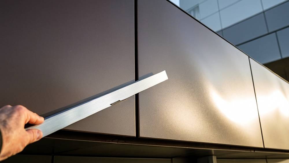
- Straight-edge measurement. A 2 m aluminium straight edge with a feeler gauge or taper gauge quantifies deviation. Record maximum gap and location on a panel sketch. Three measurements per panel (one near each edge parallel to the long dimension, one diagonal) provide adequate coverage for panels up to 3 m².
- Joint alignment check. Pair adjacent panels on a flat surface and check the step at the joint with a straight edge spanning both panels. This catches the cumulative tolerance stack between panel flatness and sub-frame alignment before it becomes a field problem.
- Documentation. Photograph each panel against a reference grid or with the straight edge in place and a scale visible. These photos become the benchmark against which installed appearance can be compared — and they are invaluable if a dispute arises later.
Contractors who perform this inspection at the laydown yard, rather than waiting until panels are hoisted to the 12th floor, save rework costs that can exceed the panel unit price by the time access equipment, labour, and schedule delay are accounted for.
Flatness is not a coating property, not a mill certificate line item, and not a structural calculation output. It is a fabrication outcome that must be specified, measured, and verified at every stage from raw sheet to installed wall. The specifier who treats it as such will get the facade the rendering promised.
Getting aluminum cladding exterior panels to lie flat on a building is a system-level challenge. It starts with specifying mill flatness per ASTM B209 or EN 485-3, continues through fabrication process control — stiffener design, weld sequencing, adhesive selection — and culminates in a post-coating flatness measurement protocol tied to an installed mock-up viewed under representative lighting. Each of these steps costs something, and each one omitted increases the probability that the first conversation after panel installation is not about how good the building looks, but about why the wall appears wavy. For specifiers and procurement teams sourcing solid aluminium panels internationally, the difference between a flat facade and an oil-canned one often comes down to whether the purchase order includes a single sentence: "Finished panels shall not deviate more than 3 mm from a true plane when measured with a 2 m straight edge after coating."