How Perforated Building Facades Open Area From 5 to 60 Percent Shapes Your Installed Cost
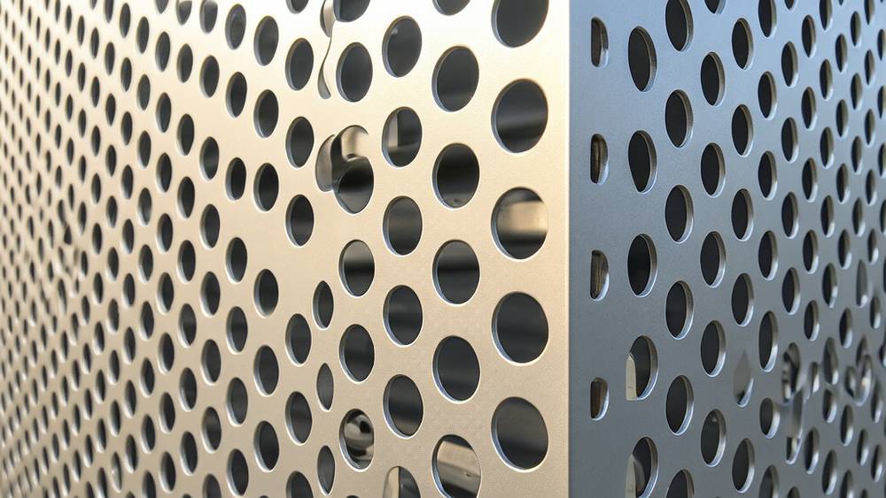
Perforated building facades have moved well beyond their original role as simple screening elements. What project teams often underestimate is how dramatically perforation geometry governs the final installed cost, the shading effectiveness, and the long-term maintenance burden of a solid aluminium cladding system. A facade with 15% open area and 6 mm round holes performs entirely differently from one with 40% open area and 25 mm staggered slots — not just visually, but structurally and economically. This distinction sits at the heart of a specification decision that carries consequences across fabrication, wind load distribution, cleaning access, and even bird ingress risk. Drawing on real project data and fabrication shop floor experience, this article maps out the cost-performance curve that architects and facade contractors navigate when they move from low to high open-area perforated building facades, with a particular focus on solid aluminium panels in the 2.5 mm to 3.0 mm thickness range.
Why Perforated Building Facades Create a Cost Curve, Not a Flat Line
The instinct is to treat perforation as a binary choice: the panel is either perforated or it is not. In practice, perforated building facades exist on a continuum defined by open area percentage, hole diameter, pitch spacing, and panel gauge. Each of these variables shifts the fabrication cost, the amount of raw material lost to scrap, the structural subframe requirements, and the thermal performance of the assembly. The relationship is not linear. A panel with 20% open area does not cost twice as much to perforate as a panel with 10% open area — the tooling setup, machine cycle time, and scrap handling costs follow their own logic.
Three interrelated factors form the backbone of the cost curve for perforated building facades:
- Punch tool wear and cycle time: Smaller holes at tighter centres mean more hits per square metre. On a CNC turret punch, a 1,200 mm × 2,400 mm panel with 8 mm holes at 12 mm staggered centres requires roughly 20,000 individual strikes. Tool life drops, machine time increases, and per-panel cost rises sharply below 10 mm hole diameters.
- Material yield: Every hole removes metal that the fabricator paid for. At 35% open area, more than one-third of the aluminium sheet becomes scrap. The scrap value of 3003-H14 or 5052-H32 aluminium offsets some of this loss, but the net material cost per usable panel area climbs with open area percentage.
- Panel flatness retention: Perforating relieves internal stresses in the sheet unevenly. Panels with high open area percentages, particularly those exceeding 40%, are more prone to warping during fabrication and require additional flattening passes or stiffener reinforcement.
These variables do not show up on a typical specification schedule. They emerge during the value engineering phase, often catching contractors off guard when tender prices come back 25-30% higher than preliminary estimates based on solid panel rates. Understanding where a project sits on the cost curve before finalising the perforation pattern is the single most effective way to keep the budget grounded.
Open Area Percentage: The Primary Driver of Installed Cost
Open area percentage — the ratio of void space to total panel surface — is the most accessible variable to adjust, and the one with the greatest financial leverage. A shift from 20% to 35% open area can increase the per-square-metre fabrication cost by a factor of 1.4 to 1.8, depending on hole geometry and sheet thickness.
The table below captures the cost-performance relationship across four common open-area ranges for solid aluminium perforated facade panels. Cost multipliers are expressed relative to a baseline solid 2.5 mm aluminium panel with PVDF coating, and represent the combined effect of material, perforation labour, scrap handling, and secondary flattening operations.
| Open Area Range | Typical Hole Diameter | Fabrication Cost Multiplier (vs Solid Panel) | Shading Coefficient | Panel Flatness Risk | Common Application |
|---|---|---|---|---|---|
| 5% – 15% | 6 mm – 10 mm | 1.25 – 1.50× | 0.85 – 0.92 | Low | Accent screens, partial privacy zones |
| 16% – 30% | 10 mm – 16 mm | 1.50 – 2.00× | 0.65 – 0.82 | Moderate | Parking structure facades, solar shading |
| 31% – 45% | 16 mm – 25 mm | 2.00 – 2.80× | 0.40 – 0.60 | High | Double-skin facades, ventilated rainscreens |
| 46% – 60% | 25 mm – 40 mm slots | 2.80 – 3.80× | 0.20 – 0.38 | Very High | Decorative outer skins, artistic installations |
Shading coefficients in the table are approximate values for a single-skin perforated screen positioned 150 mm to 300 mm in front of a sealed inner wall. The actual solar heat gain reduction depends on the cavity depth, the reflectance of the panel coating, and the building orientation. A perforated aluminium facade with 35% open area and a bright white PVDF coating can reduce incident solar radiation on the inner wall by roughly 55% to 65%, based on field measurements from projects in the Middle East and Southeast Asia.
Fabricators like Futeng® who run dedicated perforation lines for architectural aluminium can sometimes compress the cost multiplier at the higher open-area ranges by optimising tool paths and nesting patterns. The difference between a general metal fabricator and one with architectural facade experience can be 10-15% on the per-panel cost at 40% open area and above.
Hole Geometry and Structural Implications
Round holes are the most common and the least expensive to produce. They distribute stress evenly around the perimeter of each perforation, which helps preserve panel stiffness. Slotted, square, and custom-shaped perforations introduce stress concentrations at corners and can significantly reduce the effective bending strength of the panel.
When a solid aluminium panel is perforated, its section modulus changes in ways that standard bending stress formulas do not capture directly. A panel with 30% open area in a staggered round-hole pattern retains roughly 55-65% of its original bending stiffness, depending on hole diameter relative to sheet thickness. The same open area achieved with square holes can drop stiffness retention to 40-50%. For slotted patterns where the long axis aligns with the bending direction, stiffness loss can be even more severe.
This has direct consequences for subframe design. A solid 2.5 mm aluminium panel spanning 1,200 mm between supports might require stiffeners only at the perimeter. The same panel with 35% open area in a slotted pattern may need intermediate stiffeners at 600 mm centres, effectively doubling the subframe aluminium tonnage. The cost impact cascades: more subframe members, more brackets, more fasteners, and more installation labour.
Wind load testing becomes particularly important for perforated building facades with open areas above 30%. The perforations change the pressure distribution across the panel face. Small-scale wind tunnel tests or computational fluid dynamics (CFD) analysis can reveal whether the perforated skin experiences net pressure coefficients closer to those of an open lattice or a solid wall. The ASCE 7 standard provides guidance on partially enclosed and open structures, but most projects benefit from project-specific testing when the open area exceeds 40%.
The Scrap Equation Nobody Discusses Early Enough
The material economics of perforated building facades contain a hidden cost that tender documents rarely isolate: scrap value versus scrap volume. When you perforate a 2,500 mm × 1,250 mm × 3.0 mm aluminium sheet to 35% open area, you physically remove approximately 3.28 kg of aluminium per panel. At current aluminium market rates, the scrap value of clean 5052 alloy punch waste might recover 40-55% of the original material cost of that removed metal. But the fabricator still had to buy the full sheet, handle it through the punch line, and manage the scrap stream.
The net material cost per installed square metre of perforated facade therefore exceeds the simple "panel area × sheet price" calculation. A more accurate formula is:
Net Material Cost = (Panel Gross Area × Sheet Price/m²) − (Scrap Mass × Scrap Price/kg) + Scrap Handling Overhead
For a project with 2,000 m² of perforated facade at 35% open area, the scrap handling overhead alone — collection bins, transport, sorting to maintain alloy purity — can add €3 to €5 per square metre to the fabrication cost. This is not a large number in isolation, but on a multi-thousand-square-metre facade it aggregates to tens of thousands of euros that should appear in the cost plan from day one.
Some fabricators offer a "material credit" arrangement where the scrap value is deducted from the panel price upfront. This is worth negotiating, particularly on larger projects where the scrap tonnage is substantial. The credit typically ranges from 15% to 25% of the raw material cost for the removed portion, depending on the alloy and the cleanliness of the scrap stream.
Coating and Corrosion Considerations for Perforated Panels
Coating perforated aluminium panels introduces challenges that solid panels avoid. The edges of each perforation are cut metal, exposed and uncoated unless a post-perforation coating process is specified. The industry has two approaches, and the choice affects both cost and long-term durability.
The more economical route is pre-coat then perforate. The aluminium coil or sheet receives its PVDF or powder coating first, then goes to the punch line. This leaves the interior walls of each hole as bare aluminium. For interior applications or sheltered exterior locations, this is generally acceptable. The exposed edge is only the thickness of the sheet — 2.5 mm or 3.0 mm — and aluminium's natural oxide layer provides a degree of protection.
The more durable route is perforate then coat. The panel is punched first, then sent through the coating line where the liquid paint or powder can flow into and around each hole edge. This encapsulates the perforation walls and provides full corrosion protection. It also adds cost: the coating line must run at slower speeds to ensure coverage, and the perforations can trap coating material that must be cleared before curing. The cost premium for post-perforation coating on perforated building facades typically runs 15-25% above the pre-coat approach.
For coastal or high-humidity environments, the AAMA 2605 specification for PVDF coatings on architectural aluminium is the relevant standard. The spec requires a minimum 70% PVDF resin content in the colour coat and a minimum total dry film thickness of 30 microns for a two-coat system. On perforated panels, verifying film thickness on the hole edges requires destructive testing on sample panels — an additional quality assurance step that specifiers should call out explicitly in the coating scope.
Acoustic Performance as a Secondary Design Driver
Perforated building facades can serve as acoustic attenuation elements, but only when the perforation geometry is tuned to specific frequency ranges. The mechanism is Helmholtz resonance: each perforation acts as a small resonator whose frequency depends on the hole diameter, the sheet thickness, and the cavity depth behind the panel.
For traffic noise attenuation on urban facades, hole diameters in the 3 mm to 6 mm range with 15-25% open area, backed by a 50 mm to 100 mm air cavity containing acoustic insulation, can achieve noise reduction coefficients (NRC) of 0.50 to 0.75. This is comparable to purpose-built acoustic panels and makes perforated aluminium facades viable as combined shading and sound attenuation systems for buildings near motorways or rail corridors.
The catch is that acoustic performance and cost-efficiency pull in opposite directions. Small holes at high density — exactly what acoustic design demands — produce the highest fabrication costs. A 4 mm hole at 6 mm staggered centres generates roughly 28,000 punch hits per square metre. The tooling cost per panel jumps dramatically compared to a 16 mm hole pattern for shading-only applications. Project teams need to decide early whether acoustic performance is a genuine requirement or a secondary benefit, because the cost implications are significant enough to warrant a dedicated line item in the facade budget.
The ISO 354 standard for measuring sound absorption in a reverberation room provides the testing methodology. Specifiers who want perforated facade panels to contribute to the building's acoustic performance should request NRC values backed by ISO 354 test reports, not manufacturer estimates.
Where the Tender Gap Appears: Specification vs. Fabrication Reality
A recurring problem in perforated building facades procurement is the gap between what the architectural specification describes and what the fabricator prices. Specifications often define the perforation pattern in visual terms — "40% open area, staggered round holes" — without specifying the hole diameter, the pitch, the edge margin (distance from the hole centre to the panel edge), or the perforation layout relative to fold lines.
These omissions create pricing ambiguity. Two fabricators can interpret "40% open area, staggered round holes" differently — one with 20 mm holes at 30 mm centres, another with 25 mm holes at 37 mm centres — and arrive at different costs, different panel stiffness values, and different visual appearances. The tender comparison becomes meaningless because the bids are not technically equivalent.
A fabrication-ready perforation specification should include:
- Hole diameter in millimetres, with a tolerance (typically ±0.1 mm for architectural perforations)
- Pitch — centre-to-centre spacing in both directions, or a clear statement of staggered versus inline pattern
- Open area percentage calculated from the above, not stated as an independent target
- Edge margin — minimum distance from any hole centre to the panel perimeter or fold line (typically 1.5× hole diameter)
- Perforation zone — whether perforations extend to panel edges or stop short of fold lines and stiffener attachment points
- Coating sequence — pre-coat or post-perforation coating, with clear acceptance criteria for hole-edge coverage
Supplying this information at the tender stage eliminates the ambiguity that causes bid spreads of 20-30% on perforated facade packages. It also gives the structural engineer the data needed to calculate panel stiffness and subframe loads accurately, rather than applying a generic reduction factor.
Thermal Performance: Perforation as Passive Cooling
The thermal benefit of perforated building facades operates on two levels. The first is direct solar shading: the perforated skin intercepts solar radiation before it reaches the inner wall, reducing the cooling load on the building. The second is convective ventilation: the cavity between the perforated skin and the inner wall acts as a thermal chimney, drawing cooler air in at the bottom and exhausting warm air at the top.
The shading effect is straightforward to quantify. A perforated aluminium screen with a 0.50 shading coefficient cuts the solar heat gain on the inner wall by half. Combined with a ventilated cavity of 200 mm or more, the effective reduction in cooling load can reach 60-70% compared to an unshaded wall, depending on climate and orientation.
The convective benefit is harder to model with simple tools. It depends on the cavity width, the open area at the top and bottom of the facade, the perforation open area, and the temperature difference between the cavity air and the outside air. Detailed thermal modelling using tools that comply with ISO 52016 (Energy performance of buildings — Energy needs for heating and cooling) can capture these effects, but the modelling cost must be weighed against the energy savings. For commercial buildings over 5,000 m² of facade area in hot climates, the modelling investment typically pays back through reduced chiller sizing.
One practical specification point: darker PVDF colours on the perforated skin absorb more solar radiation and re-radiate it into the cavity. A dark grey perforated panel can be 20-30°C hotter than a white panel under the same solar conditions. This matters because the hotter skin heats the cavity air, reducing the convective cooling effect. Specifiers chasing thermal performance should consider light colours or high-reflectance coating formulations for the perforated outer skin, even if the architectural intent favours darker tones.
Panel Size, Stiffener Strategy, and Handling Risk
Large-format perforated panels — those exceeding 1,500 mm in any dimension — introduce handling challenges that solid panels do not. The perforations create thousands of local stress points where bending during lifting can initiate permanent deformation. A 3,000 mm × 1,500 mm × 2.5 mm panel with 35% open area weighs roughly 28-32 kg, which is manageable by a two-person lift, but the reduced stiffness means it flexes more during handling than a solid panel of the same dimensions.
Three strategies mitigate handling damage on perforated building facades:
- Perimeter stiffener frames: Welded or mechanically fixed aluminium stiffeners around the panel perimeter provide rigidity during transport and installation. For panels above 2,000 mm in the long dimension, intermediate stiffeners at 800-1,000 mm centres are standard practice.
- Increased sheet gauge: Moving from 2.5 mm to 3.0 mm aluminium adds roughly 1.35 kg/m² to the panel weight and approximately 20% to the bending stiffness. For highly perforated panels (above 40% open area), the 3.0 mm gauge often eliminates the need for one row of intermediate stiffeners, partially offsetting the material cost increase through reduced fabrication labour.
- Handling frames: Temporary lifting frames that clamp to the panel edges distribute the lifting forces and prevent localised bending. On large projects, the cost of fabricating a set of handling frames (typically €2,000-€5,000) is recovered through reduced panel damage rates.
The stiffener strategy also affects the visual appearance of the facade from oblique angles. Stiffeners behind perforated panels can create visible shadow lines if the perforation open area is high enough. At 35% open area and above, stiffeners should be positioned to align with architectural joints or shadow gaps, not randomly across the panel back, unless the cavity depth exceeds 300 mm.
Comparing Perforated Aluminium to Alternative Perforated Facade Materials
Perforated building facades can be fabricated from aluminium, steel, zinc, copper, or composite materials. Each material occupies a different position on the cost-performance curve. The table below provides a comparative overview for a typical ventilated rainscreen application with 30% open area.
| Material | Typical Gauge | Installed Cost Range (EUR/m²) | Weight (kg/m² at 30% Open Area) | Corrosion Protection Required | Design Life (Exterior) |
|---|---|---|---|---|---|
| Solid Aluminium (3003/5052) | 2.5 – 3.0 mm | €220 – €380 | 4.7 – 5.7 | PVDF or powder coat | 30 – 50 years |
| Galvanised Steel | 1.5 – 2.0 mm | €160 – €280 | 8.2 – 11.0 | Hot-dip galvanising + paint | 20 – 35 years |
| Stainless Steel (304/316) | 1.5 – 2.0 mm | €350 – €600 | 8.2 – 11.0 | None (316 for coastal) | 50+ years |
| Zinc (Titanium-Zinc) | 0.7 – 1.0 mm | €280 – €450 | 5.0 – 7.2 | Natural patina | 40 – 60 years |
| Copper | 0.6 – 1.0 mm | €350 – €550 | 5.3 – 8.9 | Natural patina | 60 – 100 years |
Aluminium occupies the middle of the cost range but offers the best strength-to-weight ratio after accounting for perforation stiffness loss. For projects where the supporting structure has weight constraints — curtain wall retrofits, lightweight steel frames, or buildings in seismic zones — aluminium's low mass per square metre is a decisive advantage over steel alternatives.
Practical Specification Checklist for Project Teams
Getting perforated building facades from concept to installation without budget overruns requires decisions that are best made during schematic design, not during tender. The following checklist distils the cost-performance curve analysis into actionable specification steps:
- Lock the open area percentage early. Treat it as a cost-line item, not a design detail to be refined later. Every percentage point above 25% adds measurable fabrication cost.
- Specify hole diameter and pitch, not just open area. A 35% open area achieved with 20 mm holes at 32 mm centres costs less to fabricate than 35% achieved with 8 mm holes at 12 mm centres.
- Decide on coating sequence before tendering. Post-perforation coating adds cost but may be mandatory for coastal or high-corrosion environments. Make it a clear scope requirement, not an option for the fabricator to interpret.
- Request a stiffener layout drawing with the tender submission. This reveals whether the fabricator has understood the stiffness implications of the specified perforation pattern.
- Budget for handling frames or additional stiffeners on panels above 2,000 mm. The cost of one damaged panel during installation can exceed the cost of the handling equipment.
- Verify acoustic claims with ISO 354 test data. If the specification attributes an NRC value to the perforated facade, require a test report for the specific hole geometry, panel thickness, and cavity configuration.
The cost-performance curve for perforated building facades is navigable when the project team treats perforation geometry as a technical specification rather than a visual preference. A well-specified perforated aluminium facade delivers on shading, ventilation, and aesthetic ambition without becoming the line item that breaks the facade budget. The key is understanding that the hole pattern on the drawing carries a fabrication cost, a structural consequence, and a maintenance legacy — and pricing all three from the start.