How 16 Gauge Perforated Metal Thickness Misleads Aluminium Facade Procurement
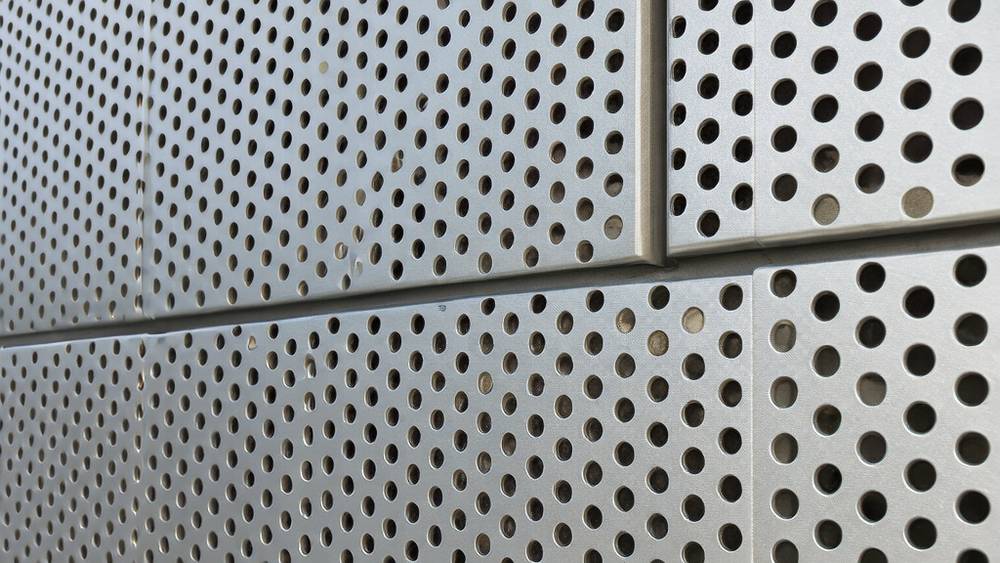
When a project specification calls for perforated cladding, the first question that lands on the procurement desk is rarely about hole diameter or open area percentage. It is about perforated metal thickness. That single number dictates whether a 3-metre panel bows under its own weight, whether a sunshade blade vibrates in a 120 km/h wind gust, and whether the perforation tooling survives a 5,000-sheet production run. This article examines how raw sheet gauge interacts with hole geometry, structural stiffness, and flatness in architectural solid aluminium cladding panels. The focus is not on generic perforated sheet sold by the pallet, but on engineered facade elements where 0.5 mm can separate a panel that stays flat on a curtain wall from one that develops visible ripples six months after handover.
Why Perforated Metal Thickness Is Not Interchangeable With Solid Sheet Gauge
An architect specifying a 2.5 mm solid aluminium panel with 40% open area might assume they are ordering 2.5 mm material. They are not. A perforated panel with 40% open area has approximately 60% of the metal remaining. The effective bending stiffness drops by more than 60% because stiffness is a function of the moment of inertia, which depends on the continuous cross-section geometry that perforations disrupt.
The Diamond Perforated Metals handbook provides the engineering framework. For round holes in a standard 60-degree staggered pattern, the equivalent thickness of a perforated sheet can be calculated using ligament efficiency ratios. A sheet with 40% open area in this pattern may behave structurally more like a 1.8 mm solid sheet than a 2.5 mm one. This is not a minor adjustment. It means the specifier who blindly selects the same perforated metal thickness as the adjacent solid panel has effectively downgraded the structural grade of their facade without realising it.
For solid aluminium cladding sourced from mills compliant with EN 485 and ASTM B209, this gap between nominal and effective thickness must be closed early. Otherwise, the panel that passed the visual mock-up on a calm Tuesday morning becomes a warranty claim by Friday afternoon when the first strong breeze hits the east elevation.
The 60-Degree Staggered Pattern and Its Hidden Thickness Penalty
Round holes on a 60-degree staggered centre is the default perforation layout in global architectural metal supply chains. It maximises open area while maintaining reasonable sheet integrity. But it creates an asymmetric stiffness problem that most project specifications ignore.
In a staggered pattern, the shortest ligament the continuous metal bridge between two adjacent holes runs at 60 degrees to the panel edges. When the panel spans vertically between floor slabs, the primary bending stress travels parallel to the panel edges. The staggered ligament is now at an angle to the stress path. The effective load-bearing metal cross-section is narrower than it appears because the critical ligament is measured perpendicular to the stress direction, not along the hole centreline.
A 2.0 mm perforated sheet with 8 mm holes on 12 mm staggered centres looks robust on a data sheet. In practice, the diagonal ligament may be just 2.5 mm wide. At 1.5 mm perforated metal thickness, that same ligament becomes a slender column prone to local buckling under compression from thermal expansion. This is where the standard gauge charts from suppliers like Marco Specialty Steel become essential: they list the minimum web width between perforations for each gauge, and ignoring those minimums is the fastest route to a rejected facade inspection.
Gauge Confusion: Why the Same "16 Gauge" Means Different Thicknesses
One of the most persistent procurement errors in international perforated cladding projects stems from gauge tables. A specification written in the United States calling for "16 gauge perforated aluminium" does not translate to the same decimal thickness as a European order referencing 16 gauge. The Manufacturers' Standard Gauge for steel, the U.S. Standard Gauge for stainless steel, and the Brown & Sharpe gauge for aluminium are three entirely different scales.
For aluminium specifically, the B&S gauge table applies. 16 gauge aluminium under B&S measures 1.29 mm. But a contractor accustomed to steel gauges might expect 16 gauge to mean 1.52 mm. That 0.23 mm gap represents an 18% reduction in perforated metal thickness from what was assumed at tender stage. Across 2,000 square metres of perforated sunshade fins, that discrepancy can cascade into deflection failures, connection overstress, and a very expensive site dispute.
The safe practice is to eliminate gauge references entirely from architectural specifications and procurement documents. State the decimal thickness in millimetres, reference the applicable material standard EN 485 for wrought aluminium or ASTM B209, and require mill certificates that confirm the as-delivered gauge. The perforation supplier then works from a verified substrate, not an interpreted number.
| Gauge System | Material | "16 Gauge" Actual Thickness | Common Confusion Point |
|---|---|---|---|
| Brown & Sharpe (B&S) | Aluminium, Copper, Brass | 1.29 mm (0.0508 in) | Often mistaken for steel gauge by non-specialist buyers |
| Manufacturers' Standard | Carbon Steel | 1.52 mm (0.0598 in) | Not applicable to aluminium; causes 18% overestimation |
| U.S. Standard | Stainless Steel, Monel | 1.59 mm (0.0625 in) | Thickest of the three; worst error if applied to aluminium |
| Metric (Preferred) | All | Specify directly: 1.5 mm, 2.0 mm, 2.5 mm, 3.0 mm | Eliminates gauge ambiguity entirely |
Open Area Percentage and the Real Cost of Getting Thickness Wrong
Open area percentage is the ratio of hole area to total sheet area. It is the number that drives visual transparency, ventilation performance, and solar shading coefficients. But it also drives cost in ways that project budgets frequently miss.
A 3.0 mm solid aluminium panel punched to 35% open area loses 35% of its material mass. The weight per square metre drops from approximately 8.1 kg to 5.27 kg. That looks like a material saving on paper. In reality, the perforation process on thicker material costs more per hole because the punching tools wear faster and the press cycle slows down. A 3.0 mm sheet with small 5 mm holes on tight centres requires significantly more tooling force and generates more heat at the punch tip than a 1.5 mm sheet with the same pattern.
The procurement trap is specifying a heavy perforated metal thickness to solve a stiffness problem that could have been addressed by adjusting the hole pattern or adding discreet stiffening ribs. A 2.5 mm panel with 50% open area may weigh and cost nearly as much as a 2.0 mm panel with 30% open area, but the latter may actually perform better structurally because it retains more metal in the critical load paths. The open area percentage and the gauge must be evaluated together. Neither number alone tells the full story.
Suppliers such as Futeng® who run dedicated perforation lines for architectural aluminium can provide the press tonnage data and tooling cost breakdowns that help project teams navigate this trade-off before the shop drawings are locked.
Flatness After Perforation: The Thickness-Dependent Problem Nobody Tests
Perforating a flat aluminium sheet introduces residual stresses. Each punch stroke compresses and shears the metal locally around the hole perimeter. When thousands of holes are punched across a 1,220 mm × 2,440 mm sheet, the cumulative stress can bow the panel by several millimetres. This is not a material defect. It is a process outcome that varies directly with perforated metal thickness.
Thinner sheets 1.0 mm to 1.5 mm are more prone to distortion because they have less inherent stiffness to resist the punching forces. Thicker sheets 2.5 mm and above resist distortion better during perforation but may require post-punch levelling that adds cost and lead time. The sweet spot for architectural flatness on perforated solid aluminium facade panels typically lands between 2.0 mm and 2.5 mm, depending on the hole size, pitch, and panel dimensions.
The problem is that most project specifications call out flatness tolerances for solid sheet per ASTM or EN standards, but those standards do not account for the post-perforation condition. A panel that measures within 0.5 mm flatness before perforation may exhibit 3 mm of deviation after. A separate flatness acceptance criterion for perforated panels should be written into the specification, and a pre-production sample should be measured on a granite surface plate before full production begins.
Wind Load and the Effective Section Modulus of Perforated Panels
Curtain wall engineers calculate required panel thickness based on wind pressure, span dimensions, and allowable deflection typically L/175 or L/240 for aluminium cladding. The section modulus of a solid rectangular panel is straightforward: width multiplied by thickness squared, divided by six. For a perforated panel, that simple formula no longer holds.
The Diamond Perforated Metals handbook provides equivalent solid material thickness factors for round-hole perforated sheets in the standard 60-degree staggered pattern. For a sheet with 40% open area, the effective thickness factor for bending is approximately 0.72. Applied to a nominal 2.5 mm perforated metal thickness, the effective bending thickness becomes 1.8 mm. The section modulus drops accordingly by roughly 48%.
A facade engineer who fails to apply this reduction has effectively designed a panel with half the intended bending resistance. The panel may not fail catastrophically, but it will deflect beyond allowable limits under design wind load, potentially causing gasket disengagement at the perimeter framing, water ingress at driving rain joints, or visible waviness that triggers an aesthetic rejection from the client's representative.
For reference, the relevant design guidance can be found through the Diamond Perforated Metals Handbook, which remains one of the few publicly available resources that quantifies the strength reduction factors for perforated sheet. The American Institute of Steel Construction also provides design methods for perforated members, though these are primarily for structural steel sections rather than thin-gauge architectural sheet.
Corner Radius and Hole Edge Quality: Why Thickness Limits Exist
Perforation tooling has physical limits. The punch diameter should generally be equal to or greater than the material thickness. Attempting to punch a 1.5 mm diameter hole through 2.0 mm aluminium risks tool breakage, poor hole edge quality, and excessive burr formation. The rule of thumb in the perforating industry is a minimum hole diameter of 0.8 times the perforated metal thickness for aluminium, though 1.0 times is safer for production volumes.
Burr height is another thickness-dependent variable. Thicker material punched with worn tooling produces larger burrs that must be removed by additional processes grinding, tumbling, or chemical deburring. For architectural panels receiving a PVDF or powder coat finish, burrs create coating voids and potential corrosion initiation points. The specification should address burr limits explicitly, referencing the Maximum Burr Height tolerances from Marco Specialty Steel's perforated metal spec information or equivalent supplier data sheets.
Thermal Movement and Perforated Panel Connections
Aluminium expands at approximately 0.024 mm per metre per degree Celsius. A 3-metre perforated panel subjected to a 60°C temperature swing from a cold winter night to direct summer sun will attempt to grow by 4.3 mm. Solid panels accommodate this movement through slotted connections and sliding clips. Perforated panels introduce an additional variable: the reduced metal cross-section concentrates thermal stress into the remaining ligaments.
If the perforated metal thickness is specified too thin relative to the panel dimensions, the ligaments between holes may buckle locally under compressive thermal stress before the panel can slide freely at its connections. This manifests as a subtle washboard effect across the panel surface, most visible under glancing light conditions. The fix is not necessarily a thicker sheet. It can be a revised hole pattern that leaves wider ligaments in the primary thermal movement direction, or a connection detail that provides lower sliding resistance.
This interaction between perforation geometry, material gauge, and connection design is rarely addressed in standard specification sections. It falls into the gap between the architect's perforation schedule and the structural engineer's connection calculations. A competent facade contractor will identify this risk during the shop drawing review and propose adjustments before fabrication begins.
Coating Coverage Inside Perforation Holes
PVDF and polyester powder coatings are applied to the visible face of perforated panels, but the interior surface of each hole presents a coating challenge. Spray application achieves limited coverage inside holes, especially on thicker material where the hole depth-to-diameter ratio is high. A 2.5 mm thick panel with 3 mm holes has a hole aspect ratio of 0.83, meaning the coating must travel nearly the full hole diameter to reach the midpoint of the hole wall.
This matters because the cut edge inside each hole is bare aluminium exposed to the environment. In coastal or industrial atmospheres, this can lead to edge creep corrosion that undermines the coating from within the hole. The solution is either a pre-treatment process that provides adequate corrosion protection on cut edges, or specifying a perforated metal thickness that keeps the hole aspect ratio below 0.5, allowing better coating penetration.
The ANB Metal perforated sheet specifications resource provides useful reference data on coating compatibility with different perforation geometries, though project-specific testing is always recommended for exposed architectural applications.
Standard Panel Sizes and the Thickness-to-Span Ratio
The industry standard perforated panel size of 1,220 mm × 2,440 mm (4 ft × 8 ft) derives from the dimensions of the raw aluminium sheet entering the perforation press. Custom sizes up to 1,500 mm × 4,000 mm are achievable on larger presses, but the wider the panel, the more critical the thickness-to-span ratio becomes.
A rule of thumb from perforated metal engineering practice: for a simply supported perforated aluminium panel spanning 1,200 mm, the minimum recommended perforated metal thickness is approximately 2.0 mm for panels with up to 30% open area. At 40% open area, the recommended minimum rises to 2.5 mm. At 50% open area, 3.0 mm becomes the practical minimum for maintaining acceptable deflection under typical facade wind loads. These are starting points, not substitutes for project-specific structural calculations.
For panels with edge stiffening returns or integrated stiffener profiles, thinner gauges become viable. A 1.5 mm perforated panel with 25 mm folded returns on all four edges may outperform a flat 2.5 mm panel without returns. The thickness decision cannot be separated from the fabrication approach.
Perforated metal thickness is not a standalone specification item. It is one variable in a system that includes hole geometry, open area, panel dimensions, edge detailing, connection design, coating specification, and wind load requirements. Change one, and the required thickness may shift.
Procurement Checklist for Perforated Aluminium Cladding Thickness
Before issuing a purchase order for perforated solid aluminium panels, the following questions should have clear, documented answers. These are the items that, when left unresolved, generate the majority of site disputes and cost overruns on perforated facade projects.
- Decimal thickness specified in millimetres? Gauge references removed. Mill certificate required.
- Effective bending thickness calculated? Open area reduction factor applied per Diamond Perforated Metals or equivalent engineering reference.
- Post-perforation flatness tolerance defined? Separate from solid sheet flatness. Pre-production sample measured and approved.
- Minimum hole diameter verified against material thickness? Ratio of 0.8:1 minimum, 1:1 recommended for production volumes.
- Burr height limit specified? Critical for coated panels. Deburring process confirmed.
- Thermal movement capacity checked? Ligament width adequate for expected temperature range with connection slide allowance.
- Coating coverage inside holes addressed? Pre-treatment spec or aspect ratio limit applied for corrosive environments.
- Tooling cost and lead time confirmed? Custom punch patterns add 2-4 weeks to delivery schedules.
When these items are addressed during the design development phase rather than during the submittal review, the project avoids the costly cycle of redesign, resampling, and production delays that plague perforated cladding packages. The perforated metal thickness number on the specification sheet is only as reliable as the engineering that surrounds it.