Aluminum Ceiling Panel Gauge How Thickness Affects Flatness and Installed Cost
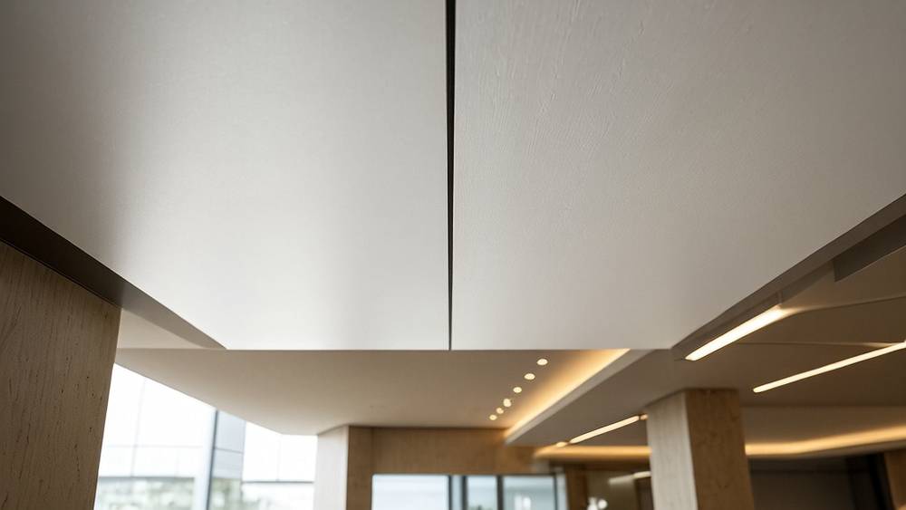
When a commercial ceiling system fails, the root cause is rarely the aluminum ceiling panel itself. More often, the problem traces back to a single overlooked variable: panel gauge. Specifying 0.8 mm where the span demands 1.2 mm leads to deflection. Choosing 1.5 mm where weight restrictions cap at 1.0 mm triggers structural overload on the suspension grid. The margin between a ceiling that holds flat for two decades and one that sags within two years lives in fractions of a millimeter.
This article isolates the gauge decision from the broader noise of ceiling specification. It is not a general guide to aluminum ceiling panels. It addresses one question that procurement managers, facade engineers, and quantity surveyors encounter on every mid-to-large-scale commercial project: what actual thickness does the job require, and what are the measurable consequences of getting it wrong? The analysis draws on ASTM standards, real per-square-meter weight differentials, acoustic data, and installed cost figures from the international supply chain — including panel sourcing from manufacturers such as Futeng®.
Why Panel Thickness Is a Structural Decision, Not an Aesthetic One
Architects often treat gauge as a visual preference. A thinner panel reads sleeker. A thicker panel implies substance. But the aluminum ceiling panel is a spanning element. It carries its own dead load across the distance between suspension points. It must resist negative wind pressure in exterior soffit applications. It must remain flat under thermal cycling, building movement, and — in some cases — the weight of acoustic fleece or integrated lighting modules.
The governing standard for panel flatness tolerance comes from ASTM B209, which specifies permissible deviation for aluminum sheet. For a 600 mm × 600 mm panel, a 0.7 mm gauge sheet will exhibit measurable oil canning under as little as 15–20°C thermal differential if the perimeter fixing is too rigid. The same panel at 1.0 mm, with identical temper (H14 or H44), reduces center deflection by roughly 35–40% under equivalent thermal load — a difference that is visible to the naked eye under raking light.
Contractors who have managed high-end commercial lobbies know this pattern. The ceiling looks flawless at handover. Six months later, under HVAC cycling and seasonal humidity shifts, ripples emerge. The client notices. The snag list grows. The root cause is not workmanship. It is a gauge that was adequate on paper but inadequate under real building physics.
Reading the Gauge Range: 0.5 mm to 3.0 mm in Practice
The aluminum ceiling panel market spans a wide gauge spectrum, but not every thickness makes sense for every application. Understanding where each gauge belongs — and where it becomes a liability — is the starting point for intelligent specification.
At the thin end, 0.5 mm to 0.6 mm panels exist almost exclusively for interior clip-in tile systems on concealed T-grids. These panels are not structural. They rely entirely on the grid for support across all four edges. Their advantage is weight: a 0.5 mm panel weighs approximately 1.35 kg/m², compared to 2.70 kg/m² for 1.0 mm. For a 5,000 m² office ceiling, that is a dead-load saving of 6.75 metric tonnes across the suspension system — a meaningful number when the grid itself has a load limit, typically 5–7 kg/m² for standard 15 mm T-bars under ASTM C635.
Moving up, 0.8 mm to 1.0 mm represents the workhorse range for commercial interiors: open-plan offices, retail, education, healthcare corridors. At this gauge, the aluminum ceiling panel can span 600 mm edge-to-edge with acceptable deflection (typically under L/360 per industry practice). Perforation patterns for acoustic absorption — commonly 2.5 mm diameter holes at 16–23% open area — remain structurally viable because the material has enough residual cross-section to resist buckling around the perforation field.
The 1.2 mm to 1.5 mm range marks the transition into semi-structural territory. Soffit panels, exterior canopy linings, and panels exceeding 1,200 mm in any dimension typically demand this gauge. Wind uplift on an exterior soffit can generate negative pressures of 0.5–1.2 kPa depending on building height and exposure category. A 1.2 mm aluminum ceiling panel on a properly engineered carrier system handles this without permanent deformation. A 0.8 mm panel will not.
At 2.0 mm to 3.0 mm, the conversation shifts to solid aluminum cladding panels used in high-wind zones, transport infrastructure (airport terminals, rail concourses), and anywhere that impact resistance matters. These panels are effectively mini-cladding elements mounted overhead. Their weight — 5.4 kg/m² at 2.0 mm, 8.1 kg/m² at 3.0 mm — demands a heavy-duty suspension system, often custom-engineered steel subframes rather than standard ceiling grid.
Gauge, Weight, and the Hidden Suspension Cost
Every millimeter of panel thickness adds dead load that the suspension system must carry. This relationship seems obvious but is frequently underestimated in early-stage budgeting. A 1.0 mm aluminum ceiling panel at 2.70 kg/m² on a standard 38 mm T-grid (load capacity ~6.3 kg/m²) leaves roughly 3.6 kg/m² for insulation, acoustic pads, and service integration before the grid reaches its limit. Jump to 1.5 mm (4.05 kg/m²) and the residual capacity drops to 2.25 kg/m² — insufficient for a dense acoustic fleece or integrated sprinkler trim.
| Panel Gauge | Weight (kg/m²) | Typical Span Limit | Required Grid System | Relative Grid Cost |
|---|---|---|---|---|
| 0.5 mm | 1.35 | 400 mm (4-edge supported) | Standard 15 mm T-bar (ASTM C635) | Baseline |
| 0.8 mm | 2.16 | 600 mm (clip-in or lay-in) | Standard 15 mm or 24 mm T-bar | +5–10% |
| 1.0 mm | 2.70 | 600 mm, limited 1200 mm with stiffener | Intermediate 24 mm T-bar or hat channel | +15–25% |
| 1.2 mm | 3.24 | 800–1200 mm (with carrier rail) | Heavy-duty 32–38 mm grid or channel | +30–45% |
| 1.5 mm | 4.05 | 1200 mm+ (with engineered subframe) | Custom steel subframe required | +50–75% |
| 2.0 mm | 5.40 | 1500 mm+ (structural soffit) | Engineered steel support system | +80–120% |
| 3.0 mm | 8.10 | 2000 mm+ (high-wind exterior) | Bespoke structural steel framing | +150–200% |
The cost implication is stark: specifying 1.5 mm where 1.0 mm would suffice does not just increase panel material cost by roughly 50% — it can more than double the installed system cost once the heavier grid, additional hangers, and longer installation hours are accounted for. On a 10,000 m² project, this difference can exceed $150,000 USD. The decision deserves more than a default specification copied from a previous project.
Acoustic Performance and the Gauge Trade-Off
Perforated aluminum ceiling panels serve a dual function: aesthetic ceiling finish and acoustic absorber. The acoustic performance depends on perforation ratio, hole diameter, and the presence of an acoustic fleece backing. But panel gauge also plays a role — and it creates a tension between acoustic and structural priorities.
Thinner gauges (0.5–0.8 mm) produce less sound reflection because the panel itself has lower mass. However, they also exhibit greater self-resonance, which can introduce unwanted vibration under certain frequency ranges — particularly in spaces with significant low-frequency noise such as transit concourses or mechanical plant rooms. A 0.6 mm panel with 20% open area can achieve a Noise Reduction Coefficient (NRC) of 0.70–0.85 when backed with acoustic fleece, measured per ASTM C423. But that same panel, if spanning 600 mm, may audibly buzz at 60–80 Hz when a train passes beneath a station concourse.
Moving to 1.0 mm shifts the resonant frequency upward and reduces amplitude, largely eliminating audible vibration in most commercial environments. The trade-off: slightly higher sound reflection from the unperforated areas. In practice, the NRC difference between a 0.7 mm and 1.0 mm panel with identical perforation patterns is typically under 0.05 — negligible in most specifications. The practical acoustic benefit of the thicker gauge is not a better NRC number but the elimination of vibration-related complaints during commissioning.
For large-format acoustic panels (panel dimensions exceeding 1,200 mm × 600 mm), 1.2 mm becomes the practical minimum. Below this, the panel's own resonance becomes difficult to control without adding stiffening ribs — which block perforations and reduce the effective acoustic area.
Flatness Tolerance: What the Eye Sees and the Standard Measures
Ceiling flatness is judged by the human eye, not by a straightedge. A panel that passes a 3 mm under 2 m tolerance check under ASTM B209 can still look wavy under grazing light from perimeter windows or cove lighting. This is the gap between measured flatness and perceived flatness — and gauge is the strongest lever for closing it.
The mechanism is straightforward. Thinner aluminum sheet has lower bending stiffness. Stiffness is proportional to the cube of thickness: a 1.2 mm panel is roughly 3.4 times stiffer in bending than a 0.8 mm panel of the same alloy and temper (stiffness ∝ t³). This means a 0.8 mm panel under identical fixing conditions and thermal load will exhibit over three times the center deflection of a 1.2 mm panel.
Specifiers working on galleries, museums, high-end retail, or corporate headquarters — spaces where lighting is carefully designed and the ceiling is a visual focal point — should treat 1.0 mm as the entry gauge and 1.2 mm as the standard recommendation for panels larger than 600 mm in any dimension. The marginal material cost (roughly $3–5 USD/m² at current international pricing) is a fraction of the cost of replacing a ceiling that the client rejects for aesthetic reasons.
Exterior Soffit: Where Gauge Meets Wind and Weather
Exterior soffit applications subject the aluminum ceiling panel to conditions that interior panels never face: wind pressure cycling, driving rain, freeze-thaw, and direct UV exposure. The gauge decision here is not about aesthetics or acoustics — it is about structural survival.
Wind load on a soffit is typically negative (uplift/suction). Per ASCE 7, the design wind pressure on soffits at building corners can reach 1.5–2.0 kPa for mid-rise buildings in Exposure Category C. A 0.8 mm panel spanning 600 mm between fixings will permanently deform under these loads. The industry consensus — reflected in manufacturer technical documentation from major systems suppliers — puts the minimum practical gauge for exterior soffit at 1.2 mm, with 1.5 mm recommended for panels exceeding 900 mm span or located above the 8th floor.
There is also the matter of fixing pull-through. Thin gauges are vulnerable to fastener heads pulling through the panel under cyclic wind suction. This failure mode is sudden: the panel appears intact, then a single fastener pulls through during a storm, creating a cascading failure as adjacent fasteners take the redistributed load. A 1.5 mm panel with properly sized washers eliminates this risk in all but hurricane-prone regions. For those zones, 2.0 mm solid aluminum panels with positive mechanical fixings — not just clip-in systems — are the defensible specification.
International Sourcing and the Gauge Verification Problem
Procurement teams sourcing aluminum ceiling panels from international suppliers face a specific challenge: verifying that the delivered gauge matches the specified gauge. It is not uncommon for panels specified at 1.0 mm to arrive at 0.85–0.90 mm — within manufacturing tolerance for some mills but below the engineering requirement for the project.
The relevant tolerance standard is ASTM B209, which permits a thickness tolerance of ±0.08 mm for sheet in the 1.0–1.5 mm range. This means a panel ordered as "1.0 mm" can legally be delivered at 0.92 mm and still conform to the standard. If the engineering calculation assumed exactly 1.0 mm, the 8% reduction in thickness translates to an approximately 22% reduction in bending stiffness — enough to cause deflection problems in borderline designs.
Experienced buyers address this with three practices. First, specify the minimum acceptable gauge rather than a nominal gauge with tolerance. Second, require mill test certificates (MTCs) per EN 10204 Type 3.1 or 3.2 that report actual measured thickness per coil or batch. Third, conduct random thickness verification using a calibrated micrometer upon receipt — particularly for large-format panels where flatness is critical. Reputable manufacturers, including Futeng®, routinely provide full MTC documentation and accept third-party inspection as a standard condition of supply.
Fire Performance: Gauge, Coatings, and the Combustibility Question
Aluminum itself is non-combustible and carries a Euroclass A1 rating in its bare form under EN 13501-1. But an aluminum ceiling panel is rarely bare metal. It carries a paint finish — typically polyester powder coat or PVDF — and may have an acoustic fleece bonded to the rear face. These additions change the fire equation.
Panel gauge matters here indirectly. Thinner panels heat through faster in a fire scenario, which can cause paint to ignite or delaminate sooner than on a thicker panel with greater thermal mass. The difference between a 0.6 mm and 1.2 mm panel in time-to-paint-ignition can be 2–4 minutes under a standard time-temperature curve — not a trivial margin in a fire engineering assessment. For projects where fire performance is a primary concern — hospitals, high-rise residential, transport tunnels — the specification should consider minimum gauge alongside coating selection and fleece material.
"In our experience across Southeast Asian infrastructure projects, the combination of 1.2 mm minimum gauge, PVDF coating, and mineral wool acoustic backing consistently meets both the structural and fire requirements without requiring trade-offs or value engineering revisions late in the program."
Making the Gauge Decision: A Practical Sequence
Rather than defaulting to a standard specification — a habit that produces both over-engineered and under-engineered ceilings across different projects — the gauge decision should follow a simple sequence of checks:
- Define the span. What is the maximum unsupported dimension of the panel? Is it supported on four edges (clip-in grid) or two edges (linear plank)? Four-edge support allows roughly 40% greater span for the same gauge.
- Identify the environment. Interior conditioned space? Interior unconditioned (warehouse, parking)? Exterior soffit? Exterior soffit in a coastal or high-wind zone? Each step upward in exposure demands roughly 0.2–0.3 mm additional gauge.
- Calculate the dead load budget. What is the suspension system's rated capacity? Subtract the panel weight, acoustic backing, insulation, and any integrated services. If the residual is under 1.0 kg/m², reconsider the gauge or the grid specification.
- Check the aesthetic requirement. Is the ceiling under direct or grazing light? Will it be viewed from close distance (under 3 m)? If yes, bias toward the thicker end of the structurally adequate range to control perceived flatness.
- Verify fire and acoustic requirements. Ensure the selected gauge, with its coating and backing system, meets the project's fire classification and acoustic targets. Adjust gauge upward if fire engineering demands greater thermal mass.
- Specify a verifiable gauge. Write the specification as a minimum thickness with a defined measurement method (e.g., "1.0 mm minimum, measured per ASTM B209 at any point on the panel excluding coating thickness") and require MTC documentation.
What the Gauge Decision Actually Costs
To ground this analysis in real project economics, consider a 5,000 m² commercial office ceiling with standard 600 mm × 600 mm clip-in panels. The estimated installed cost comparison across three common gauge options — inclusive of panels, suspension grid, hangers, and installation labor at Southeast Asian or Middle Eastern market rates — breaks down as follows.
| Cost Element | 0.8 mm Panel System | 1.0 mm Panel System | 1.2 mm Panel System |
|---|---|---|---|
| Panel material (USD/m²) | $18–22 | $22–28 | $28–35 |
| Suspension grid (USD/m²) | $8–10 | $10–14 | $14–20 |
| Installation labor (USD/m²) | $12–16 | $12–16 | $14–18 |
| Total installed (USD/m²) | $38–48 | $44–58 | $56–73 |
| 5,000 m² project total | $190K–$240K | $220K–$290K | $280K–$365K |
| Flatness risk (subjective) | Moderate–High | Low–Moderate | Very Low |
| Typical application fit | Standard office, retail | Corporate, education, healthcare | Premium commercial, transport, exterior soffit |
The spread between the cheapest adequate option and the safest option is roughly $90,000–$125,000 on a 5,000 m² project. In the context of a total project value that typically runs into tens of millions, this is a modest premium for eliminating callbacks, deflection complaints, and potential replacement liability. The more expensive mistake is specifying 0.8 mm for a project that demands 1.2 mm and discovering the problem after the scaffolding is down.
The aluminum ceiling panel gauge decision is not a matter of preference, habit, or cost-minimization in isolation. It is an engineering choice with measurable structural, acoustic, fire, and financial consequences. The correct gauge is the one that satisfies all relevant constraints at the lowest total installed cost — not the one that costs least per square meter on the purchase order. For the procurement manager, the contractor, and the specifier, the discipline is to run the checks, verify the delivered product, and resist the temptation to treat gauge as a copy-paste field from the last project specification.