Why Perforated Metal Patterns Dissolve at 30 Metres and How to Specify Against It
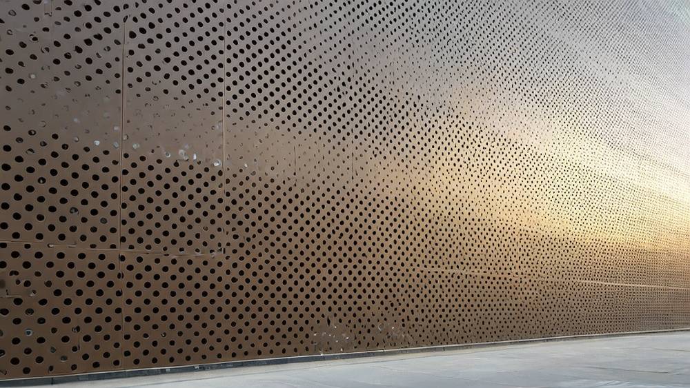
Specifying perforated metal for architectural cladding and interior fit-outs presents a recurring headache that few project teams anticipate: the hole you see on a 100 mm sample swatch does not scale the way you think it does. A 12 mm round perforation on a 1.5 mm aluminium sheet looks crisp and deliberate at arm's length. Multiply that by 800 panels covering a 2,400 m² elevation, viewed from 18 metres across a plaza, and the same hole pattern can dissolve into a grey haze, losing all definition and transforming a carefully designed geometric motif into what reads visually as a solid surface with a slight texture. This phenomenon — the breakdown of perforation legibility at architectural scale — drives more value-engineering rework, shop-drawing revision cycles, and on-site disappointment than almost any other single variable in ventilated rainscreen design. Getting it right requires moving beyond aesthetic preference and into the physics of viewing distance, open area percentage, and the relationship between sheet gauge and hole diameter that governs both structural integrity and visual performance.
The Viewing Distance Problem Nobody Discusses at Design Stage
Architects routinely specify perforated metal based on a physical sample or a rendered elevation viewed on a 27-inch monitor. Both are misleading. A physical sample measuring 200 mm × 200 mm gives no indication of how the pattern reads at 10 metres, 20 metres, or 50 metres. A rendering, even a high-quality one, typically overstates contrast and understates the optical blending that occurs when the human eye resolves thousands of small apertures from a distance.
The underlying mechanism is spatial resolution of the human visual system. The average person with 20/20 vision can resolve two points as distinct when they subtend an angle of approximately 1 arcminute, or 1/60th of a degree. At 10 metres, that equates to about 2.9 mm — meaning any two hole edges closer than that will blur together. At 30 metres, the minimum resolvable separation jumps to roughly 8.7 mm. A perforated metal panel with 6 mm diameter holes on 9 mm staggered centres, viewed from 30 metres away, ceases to read as individual perforations. The eye integrates the open and solid areas into a single averaged tone.
This is not a manufacturing defect. It is not a finishing problem. It is basic optics, yet it blindsides project teams because the conversation about viewing distance rarely happens before the perforation pattern is locked into the specification.
Open Area Percentage and Perceived Brightness
The second variable interacting with viewing distance is open area percentage — the ratio of hole area to total sheet area, expressed as a percentage. A perforated metal sheet with 23% open area does not simply appear as "a darker solid with holes." From a distance where individual perforations are unresolvable, the panel reads as a uniform surface with an apparent reflectance roughly proportional to the weighted average of the solid metal reflectance and whatever lies behind the panel.
This has cascading consequences. When perforated metal is installed as a rainscreen over a dark insulation layer or a black weather barrier, a 23% open area panel can read 30-40% darker than the same aluminium alloy in solid form, because the dark substrate bleeds through and mixes optically with the metal surface. Conversely, the same panel mounted 150 mm off a white waterproofing membrane can appear significantly lighter.
For project teams accustomed to specifying solid aluminium cladding panels, where colour and gloss are controlled entirely by the PVDF or powder coating specification, this substrate-dependence of perceived colour in perforated metal is an unwelcome surprise. It means that coating alone cannot guarantee the final visual result — the cavity depth, substrate colour, and lighting conditions all become co-authors of the facade's appearance.
| Viewing Distance | Min Resolvable Hole Diameter (20/20 Vision) | Pattern Legibility for 8 mm Holes on 12 mm Centres | Recommended Minimum Hole Ø for Clear Pattern Reading |
|---|---|---|---|
| 5 m | ~1.5 mm | Sharp, individual holes visible | 6 mm |
| 10 m | ~2.9 mm | Holes visible but edges softening | 8 mm |
| 20 m | ~5.8 mm | Pattern begins to blend; reads as texture | 12 mm |
| 30 m | ~8.7 mm | Individual holes largely unresolvable | 16 mm |
| 50 m | ~14.5 mm | Pattern lost; reads as tonal value only | 20 mm+ |
Gauge-to-Hole-Diameter Ratio and Why It Dictates Flatness
Beyond visual perception, there is a structural dimension to perforation specification that directly impacts panel flatness — the single most scrutinised quality metric on any completed facade. When a solid aluminium panel arrives on site with a 0.5 mm wave across its surface, the installer can often adjust the support framing to pull it flat. When a perforated metal panel arrives with the same deviation, the reduced stiffness of the perforated sheet makes mechanical correction far less forgiving.
The critical ratio is sheet thickness to hole diameter. As a practical rule developed across thousands of perforated metal facades, panel flatness becomes difficult to guarantee when the hole diameter exceeds 2.5× the sheet thickness for round holes on staggered centres with open areas above 30%. For a 2.0 mm thick aluminium sheet (a common minimum for architectural rainscreen applications), that means hole diameters above 5 mm begin to progressively reduce the panel's inherent stiffness.
This does not mean large perforations in thin material are impossible. It means the supporting framework — the perimeter stiffeners, intermediate Z-girts, and the attachment method — must compensate for what the perforation has removed. A 3.0 mm solid aluminium sheet with 40% open area in a 20 mm round-hole pattern will behave more like a 2.0 mm solid sheet in terms of bending resistance, but the stress concentrations around each hole introduce failure modes that a solid sheet does not experience.
Futeng® has addressed this in multiple projects by working with design teams to adjust either the gauge or the perforation pattern during the shop-drawing phase, rather than allowing an unbuildable specification to reach the factory floor. The conversation usually starts with sample mock-ups viewed at the actual installation distance, not the architect's desk.
Stress Concentration Around Perforations
Every hole punched or CNC-drilled into an aluminium sheet creates a stress riser. Under wind loading, the material adjacent to each perforation experiences localised stress that can be 2-3× higher than the nominal stress in the unperforated ligament between holes. This is well-characterised in mechanical engineering but often overlooked in architectural specifications for perforated metal.
For panels on high-rise elevations where wind pressures exceed 2.0 kPa (typical for building corners and parapet zones above 60 metres in many urban wind environments), the combination of high open area and thin gauge can lead to permanent deformation — not from a single storm event, but from the accumulated fatigue of thousands of wind cycles over the building's service life. The failure mode is progressive: a slight buckle near a corner perforation, which then redirects wind pressure unevenly, which then accelerates deformation in adjacent areas.
The conservative engineering approach is to maintain a minimum ligament width (the metal between adjacent holes) of at least 1.0× the sheet thickness for architectural perforated metal, and preferably 1.5× for panels in high-wind zones. This constraint often forces a trade-off between the desired open area and the achievable hole pattern, which must be resolved before the perforation tooling is manufactured.
CNC Punching vs Laser Cutting for Architectural Perforated Metal
The manufacturing method used to create perforations in aluminium sheet influences both the visual quality of the hole edge and the dimensional accuracy of the pattern — two factors that become increasingly visible as panel dimensions grow.
CNC turret punching uses hardened tool steel punches and dies to shear through the aluminium sheet. The process is fast and cost-effective for production runs above 100 m², but it leaves a characteristic slight burr on the breakout side of the hole and a small radius on the punch entry side. For perforated metal panels viewed from below — soffit applications, canopy undersides, or any elevation where the back face of the panel is visible — this burr must be removed by secondary deburring, which adds cost and lead time. The punch entry side, however, is clean and can be oriented outward for most rainscreen applications.
Laser cutting produces a cleaner hole edge with no burr and no mechanical deformation around the hole perimeter. The heat-affected zone is minimal on aluminium when using modern fibre lasers with nitrogen assist gas. However, laser-cut perforated metal is typically 3-5× more expensive per square metre than punched, and the process is inherently slower — a constraint that matters when 3,000 panels are due on site in 12 weeks.
The decision between the two methods should be driven by four factors: the required hole-edge quality (driven by viewing distance and panel orientation), the total perforated area, the project schedule, and whether the hole pattern includes non-round geometries that cannot be economically punched.
| Parameter | CNC Turret Punching | Fibre Laser Cutting |
|---|---|---|
| Edge Quality (Visible Face) | Clean punch entry; slight burr on breakout | Clean both sides; no burr |
| Typical Cost (per m², 2.0 mm Al, 25% OA) | Base + 15-25% perforation surcharge | Base + 50-80% perforation surcharge |
| Production Speed | High; suited to volumes over 500 m² | Moderate; best for complex or small-batch work |
| Minimum Hole Diameter | ~1.0× material thickness | ~0.5× material thickness |
| Non-Round Hole Shapes | Limited to available tooling; tooling cost per shape | Any programmable geometry; no tooling cost |
| Material Thickness Range (Aluminium) | 0.8 mm – 4.0 mm typical | 0.5 mm – 6.0 mm typical |
Perforation Pattern Registration Across Multi-Panel Elevations
A specification that looks flawless on a single-panel drawing can produce visually jarring results when 200 panels are installed adjacent to one another. The issue is pattern registration — whether the perforation grid aligns seamlessly from one panel to the next across the joints.
Standard industry practice for perforated metal is to punch or cut the pattern relative to each individual sheet edge, with a specified margin (unperforated border) around the perimeter. This margin is required for structural integrity — perforations too close to the panel edge create a tear-out risk during handling, fabrication, and wind loading. A 12-15 mm unperforated margin is typical for panels up to 1,200 mm wide.
The problem arises when panels are installed with a 10-20 mm open joint. The eye expects the perforation pattern to continue across the joint, but the combination of the unperforated margin on both panels plus the joint width creates a visible interruption that can be 35-50 mm wide — wider than the hole spacing itself. From a distance, this reads as a grid of horizontal and vertical lines superimposed on the perforation pattern, an effect that can either enhance or destroy the design intent depending on whether it was anticipated.
Addressing this requires a decision early in the design phase: either embrace the joint grid as a compositional element (aligning it with floor lines, column grids, or other facade rhythms) or specify panel-to-panel pattern continuity, which demands that each panel's perforation layout be positioned relative to a global grid rather than to its own edges. The latter approach increases material waste (because sheets must be oversized and trimmed to achieve pattern alignment) and demands tighter fabrication tolerances — typically ±0.5 mm on hole position rather than the ±1.0 mm that is common for non-registered work.
Acoustic Transparency vs Visual Transparency
Perforated metal is frequently specified for acoustic applications — ceiling panels, wall linings in atria, and equipment screens — where sound absorption behind the perforated layer is the primary functional requirement. The specification pitfall here is conflating acoustic transparency with visual openness.
Acoustic transparency for a perforated metal facing depends primarily on open area percentage, but the relationship is not linear. A panel with 20% open area may achieve only 60-70% acoustic transparency at mid-frequencies, while a panel with 35% open area can exceed 90%. The physics involves viscous losses as sound waves pass through small apertures — smaller holes produce greater acoustic resistance even at the same overall open area.
This means that two perforated metal patterns with identical 25% open area can have measurably different acoustic performance if one uses many small holes (e.g., 3 mm diameter on 6 mm centres) and the other uses fewer large holes (e.g., 12 mm diameter on 24 mm centres). The small-hole pattern will attenuate more high-frequency energy, which may be desirable for speech-range absorption but less effective for low-frequency noise from mechanical equipment.
The ASTM E1050 standard for impedance tube testing provides the measurement methodology, but many project specifications simply call for "acoustically transparent perforated metal" without defining the frequency range or minimum transparency threshold. This gap between specification language and measurable performance is where post-installation disputes originate.
Coating Coverage Inside Perforations
A subtle but consequential quality issue in architectural perforated metal is coating coverage on the interior walls of each perforation. When a pre-perforated aluminium sheet is sent through a liquid PVDF coating line, the spray application deposits paint primarily on the face of the sheet and the outer rim of each hole. The interior cylindrical surface of each perforation may receive only partial coverage — sometimes as little as 30-50% of the nominal dry film thickness specified for the face.
For interior applications in dry environments, this partial coverage is functionally adequate. For exterior rainscreen applications in coastal or high-humidity environments, the uncoated or thinly coated interior of each perforation becomes a corrosion initiation site. Moisture condenses inside the holes, aluminium oxide forms, and over time the visible hole edges can develop a white filiform corrosion that is cosmetically unacceptable even though it does not compromise structural integrity.
The mitigation options are: (1) specify post-perforation coating rather than coating of pre-perforated sheet, understanding that this may still leave some holes with less-than-full coverage; (2) specify powder coating, which can achieve better hole interior coverage due to electrostatic wrap-around effects; (3) use anodised aluminium for perforated panels, where the anodic layer forms uniformly on all exposed surfaces including hole interiors; or (4) accept the limitation and select a coating colour that minimises the visual impact of any edge corrosion over time — darker colours and matte finishes are more forgiving than light, glossy ones.
"On a 2019 mixed-use project in a coastal humidity zone, the perforated aluminium rainscreen panels were pre-coated in a light silver metallic PVDF. Within 18 months, pinhead-sized white corrosion spots appeared at approximately 40% of the hole edges. Investigation confirmed that hole interior DFT averaged 12 microns against the specified 30 micron minimum. The solution was not re-coating but replacing the panels with an anodised finish — at a cost exceeding the original perforated metal package by 60%. The lesson: specify coating method and verify hole interior DFT on approval samples before production begins."
Specifying Perforated Metal for Curved and Three-Dimensional Geometries
When perforated metal is specified for curved facade elements — barrel-vaulted canopies, column covers, or free-form architectural features — an additional layer of complexity enters the equation. The perforation pattern that looks regular on a flat sheet becomes distorted when the sheet is rolled or bent to a radius.
The distortion is geometric: holes near the tension face of a curved panel elongate, while holes near the compression face compress. For a 2.0 mm aluminium sheet rolled to a 500 mm radius, the strain differential between the inner and outer fibre is approximately 0.4% — small enough to be visually imperceptible for most hole patterns. But when the radius tightens to 200 mm or below, the strain can exceed 1%, and hole distortion becomes visible to the naked eye, particularly for larger-diameter perforations.
The correct fabrication sequence for curved perforated metal is to perforate the flat sheet first, then form to the required radius. Attempting to perforate a pre-curved panel is technically possible but economically impractical for all but the smallest production runs. The forming process must account for the reduced stiffness of the perforated sheet — the bending force required is lower, but the risk of localised buckling between holes is higher, particularly for patterns with narrow ligaments.
For complex doubly-curved geometries, laser-cut perforated metal offers an advantage: the cutting path can be programmed to compensate for the expected deformation during forming, so that the final hole pattern on the curved surface matches the design intent more closely than a standard punched pattern would.
Fire Performance and Perforated Metal Rainscreens
Building codes in most jurisdictions treat perforated metal facades differently from solid cladding when assessing external fire spread risk. The presence of perforations changes the ventilation characteristics of the cavity behind the rainscreen, which in turn affects how flames propagate vertically between floors.
Under the requirements of BS 8414 (UK) and NFPA 285 (US), ventilated facades with perforated metal outer layers must be tested as complete assemblies — the perforation pattern, open area, cavity depth, insulation type, and fire barriers all interact to determine whether the system passes or fails. A perforated metal panel with 40% open area may allow sufficient airflow to sustain cavity combustion that a 20% open area panel of the same material would suppress.
This is not a reason to avoid high-open-area perforated metal — it is a reason to involve the facade engineer and fire consultant before the perforation specification is finalised. The cavity fire barriers that are standard for solid cladding may need to be repositioned or supplemented for perforated systems, and the additional cost and visual impact of those barriers should be factored into the design budget from day one.
Practical Specification Checklist
The following checklist distils the key decision points that should be resolved before perforated metal shop drawings are commissioned. Each item has a direct impact on cost, lead time, or on-site visual outcome:
- Viewing distance range: Define the minimum and maximum distances from which the facade will be viewed. Use these to validate hole diameter and spacing choices with physical mock-ups, not renderings.
- Open area percentage: Specify the required range, not a single number. A range of 23-28% gives the perforator flexibility to use standard tooling and reduces cost versus an exact 25.0% requirement that demands custom punch sets.
- Sheet gauge: Confirm that the specified thickness can support the desired hole diameter and open area without excessive deflection under the project wind load. Require structural calculations for panels in corner zones.
- Perforation method: Specify CNC punching or laser cutting based on hole-edge quality requirements, volume, and budget. Do not leave this to the fabricator to decide if edge quality is critical.
- Unperforated margins: Define the margin width on all four edges. Coordinate with the joint design to ensure the visual result across panel joints matches the design intent.
- Coating sequence and hole interior coverage: Specify whether coating occurs before or after perforation. Require a minimum dry film thickness measurement inside representative holes on the approval sample.
- Pattern registration: State explicitly whether the pattern must align across panel joints (global registration) or whether each panel is perforated independently. This decision affects both cost and visual outcome.
- Mock-up requirements: Require a multi-panel mock-up viewed at the actual installation distance before production approval. A single 300 mm sample is insufficient.
Perforated metal is one of the most expressive materials available to facade designers, capable of transforming a building envelope into a calibrated filter that modulates light, view, air, and sound. The hazard lies in treating it like solid cladding with holes added as an afterthought. The hole pattern is not decoration — it is a structural, optical, acoustic, and fire-engineering parameter that demands the same analytical rigour as any other facade system component. When specified with an understanding of viewing distance optics, gauge-to-diameter ratios, manufacturing method implications, and coating coverage realities, perforated metal delivers results that match the rendering. When these variables are left unexamined until the first panels arrive on site, the gap between expectation and reality can be expensive to close. For project teams seeking a supplier who engages these questions at the shop-drawing stage rather than after production, Futeng® brings practical engineering experience to the specification conversation — not as a sales pitch, but as a safeguard against the most common and costly perforated metal specification errors.