Aluminium Cladding Panels Deflection Limits and Stiffener Spacing for 30 Year Flatness
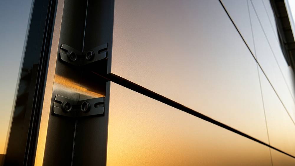
When a rainscreen facade buckles under a 120 km/h wind gust, the post-mortem rarely points to the aluminium alloy itself. More often, the failure traces back to a single calculation that was overlooked during specification: the relationship between panel gauge, stiffener layout, and maximum deflection under service load. For solid aluminium cladding panels, getting this right means the difference between a facade that stays flat for 30 years and one that develops visible pillowing within the first six months. This article unpacks what deflection limits actually mean for 2.0 mm, 2.5 mm, and 3.0 mm solid aluminium panels, how stiffener spacing changes the math, and where experienced contractors draw the line between acceptable and risky.
What "Deflection Limit" Actually Means for Solid Aluminium Facades
Deflection refers to the amount a panel bends perpendicular to its plane when subjected to wind pressure. Every aluminium cladding panel deflects under load. The question is how much deflection the system can tolerate before the movement becomes visible, causes coating stress, or compromises the rainscreen cavity behind it.
Industry practice for solid aluminium cladding panels typically references two thresholds. The first is L/60, meaning the panel's maximum deflection must not exceed one-sixtieth of its unsupported span. If a stiffener bay measures 600 mm centre-to-centre, L/60 allows 10 mm of movement under design wind load. This threshold originates from metal panel engineering where visual flatness matters but structural failure does not. The second common limit is L/90, tighter by a third, applied to projects where specular finishes (mirror-polish, high-gloss PVDF) or grazing-angle sunlight will make even minor undulations visible.
Some facade consultants push further to L/120 for premium commercial towers and airport terminals, where the client's expectations and the viewing distance combine to demand near-zero perceptible movement. This is not a code requirement in most jurisdictions; it is a performance specification driven by architectural intent.
Confusion arises when specifiers conflate deflection under design wind load with deflection under ultimate (safety) load. The L/60 or L/90 limit applies to serviceability — the wind pressure the building expects to see once every 50 years. Ultimate wind load, typically 1.5 times the service load, checks whether the panel and its fixings stay attached to the building. A panel that hits L/45 at ultimate load but stays within L/60 at service load is performing exactly as engineered.
Panel Thickness: 2.0 mm vs 2.5 mm vs 3.0 mm Solid Aluminium
Thickness is the first lever engineers pull when deflection calculations come back too high. For solid aluminium cladding panels, the relationship between thickness and stiffness is cubic: a 3.0 mm panel is not 50% stiffer than a 2.0 mm panel; it is roughly 3.4 times stiffer because stiffness scales with the cube of thickness (t³).
The table below compares the three most common gauges used in solid aluminium rainscreen fabrication:
| Property | 2.0 mm Solid Aluminium | 2.5 mm Solid Aluminium | 3.0 mm Solid Aluminium |
|---|---|---|---|
| Weight (kg/m²) | 5.4 | 6.75 | 8.1 |
| Relative bending stiffness | 1.0 (baseline) | 1.95× | 3.38× |
| Typical max unsupported span at L/90, 1.0 kPa wind | ~450 mm | ~580 mm | ~720 mm |
| Common application | Small-format panels, soffits, interior linings | Mid-rise commercial, standard rainscreen | High-wind zones, large-format panels, feature walls |
| Material cost index (per m², relative) | 1.00 | 1.22 | 1.45 |
| Fabrication complexity | Easy to bend/route; higher oil-canning risk | Balanced workability and flatness | Requires heavier tooling; best flatness retention |
The numbers tell a clear story: jumping from 2.0 mm to 2.5 mm nearly doubles stiffness, while the cost increase is only about 22%. For most commercial facades, 2.5 mm solid aluminium cladding panels represent the intersection of structural efficiency and budget sensitivity. The 3.0 mm option becomes necessary when panel dimensions exceed 1,200 mm in any direction, when stiffener attachment is constrained by the cavity depth, or when the project sits in a typhoon-prone coastal zone with design wind pressures above 2.5 kPa.
One nuance specifiers often miss: a 2.0 mm panel with closely spaced stiffeners can sometimes outperform a 3.0 mm panel with generous stiffener spacing. The stiffener layout matters as much as the base material thickness — a point explored in the next section.
Stiffener Layout: The Real Control Knob for Deflection
Stiffeners — aluminium extrusions or folded profiles bonded or mechanically fixed to the rear face of the panel — break a large unsupported area into smaller bays. Each bay behaves like a simply supported plate, and the maximum deflection within each bay determines whether the panel looks flat or wavy.
The governing principle is straightforward: halving the stiffener spacing reduces deflection by a factor of roughly 16 (since deflection is proportional to span⁴ for a uniformly loaded plate). This is far more potent than increasing panel thickness. A 2.0 mm panel on 300 mm stiffener centres will deflect less than a 3.0 mm panel on 600 mm centres under the same load.
Practical stiffener configurations seen across projects include:
- Perimeter-only stiffening: A folded return on all four edges. Suitable only for panels under 600 × 600 mm with 3.0 mm thickness. Deflection controlled by the plate bending across the open centre.
- Single central vertical stiffener: Common on 600 × 1,200 mm panels. Reduces the horizontal span by half. Works well with 2.5 mm material at moderate wind loads.
- Grid stiffening (vertical + horizontal): Creates bays of 400 × 400 mm or smaller. Required for large-format panels (1,200 × 2,400 mm and above) and high-wind facades.
- Full-bonded stiffener tray: A continuous aluminium tray adhesively bonded across the entire rear surface. Eliminates local bay deflection entirely; the panel behaves as a composite. Used on ultra-flat architectural feature walls and airport terminal facades where L/120 is specified.
The cost implication of each approach deserves attention. Perimeter-only stiffening is cheapest to fabricate but limits panel size. Grid stiffening adds labour and material — roughly 12-18% to the fabricated panel cost — but unlocks larger formats that reduce joint count and installation time. The trade-off between factory cost and site cost should be evaluated per project rather than assumed.
Futeng®, a solid aluminium cladding panel manufacturer with extensive export experience across Southeast Asia and the Middle East, routinely advises contractors to share wind tunnel data early in the design phase. When project teams delay this, the stiffener layout often gets re-engineered twice — once for the conservative code-based pressure and again when the wind consultant's report shows peak pressures concentrated at building corners that are 40% higher than the code value.
Wind Loads: From Code Numbers to Panel-Level Forces
Wind pressure is not uniform across a building facade. Corner zones (typically the outer 10% of each wall dimension) experience significantly higher suctions than the field area. ASCE 7-22 defines corner zone pressure coefficients that can be 2.0 to 3.5 times the field zone values, depending on building geometry and exposure category. A panel that comfortably meets L/90 at 1.2 kPa in the field zone may exceed L/60 at 3.6 kPa in the corner zone — a critical mismatch if the same panel specification is applied uniformly across the entire elevation.
For solid aluminium cladding panels, the practical workflow should be:
- Obtain zone-by-zone design wind pressures from the project wind engineer (not just the overall building design pressure).
- Identify the worst-case panel within each zone — typically the largest panel with the fewest stiffeners.
- Run deflection calculations for that panel using the zone-specific pressure.
- Adjust thickness or stiffener layout only for the panels that fail the check, rather than over-engineering the entire facade.
This zoned approach saves material and cost. On a 30-storey tower, corner-zone panels might represent only 15% of the total clad area. Specifying 3.0 mm material everywhere when only the corners need it adds unnecessary weight to the building structure and roughly 18% to the aluminium procurement cost. A smarter specification uses 2.5 mm across field zones and 3.0 mm with tighter stiffener spacing at corners and parapets.
The AAMA 508-20 standard provides a voluntary test method for determining the structural performance of pressure-equalized rainscreen panels under static and cyclic wind loading. While not universally mandated by building codes, referencing AAMA 508 in the project specification gives the contractor a clear, defensible benchmark for what constitutes acceptable panel performance.
Oil Canning: When Deflection Meets Perception
Oil canning — the wavy distortion visible on the surface of flat metal panels — is the most common aesthetic complaint on solid aluminium cladding panel installations. It is not a structural failure. The panel is not about to detach or leak. But in raking light, the undulations become obvious and can trigger disputes between contractor, architect, and client.
The root cause of oil canning is residual stress introduced during fabrication combined with elastic buckling under thermal expansion. When a solid aluminium sheet is roll-formed, routed, or bent, the cold-working process leaves non-uniform stress distributions locked into the material. As the panel heats up on a sunny day, thermal expansion increases compressive stress in the plane of the panel. If the compressive stress exceeds the critical buckling stress of the plate — which depends directly on thickness and bay dimensions — the panel buckles elastically into a wavy shape. When it cools, it may or may not return fully flat depending on whether the stress exceeded the material's yield point.
Thicker panels resist oil canning better, not because they expand less (thermal expansion is independent of thickness), but because their higher bending stiffness raises the critical buckling stress. A 3.0 mm panel with 400 mm stiffener bays is substantially less prone to oil canning than a 2.0 mm panel with 600 mm bays, even if both meet the same L/90 deflection limit under wind load.
The NAAMM (North American Architectural Metal Manufacturers) position paper on oil canning explicitly states that some degree of oil canning is inherent to flat metal panels and cannot be entirely eliminated. It recommends viewing distance and lighting conditions be agreed between specifier and contractor before fabrication begins. A practical benchmark: panels viewed from 6 metres under diffuse (overcast) lighting should not show perceptible waviness exceeding 2 mm deviation across any 300 mm gauge length.
Fabrication techniques that reduce oil canning risk include stress-relieving the aluminium sheet before routing, using a full bonded stiffener tray instead of point-fixed stiffeners, and specifying a stucco-embossed or lightly textured finish that optically masks minor undulations. A high-gloss mirror finish on a 2.0 mm panel with perimeter-only stiffening is the worst-case combination and should be avoided unless the panel dimensions are kept very small (under 500 × 500 mm).
Thermal Movement and Deflection: Two Forces That Compound
Solid aluminium expands and contracts at roughly 0.024 mm per metre per degree Celsius. A 3-metre-tall panel subjected to a 60°C temperature swing (from a cold winter night to direct summer sun on a dark-coloured PVDF finish) will grow by about 4.3 mm in length. If the panel fixings do not accommodate this movement, the thermal expansion force can be enormous — enough to buckle the panel or shear the fasteners.
This matters for deflection because a thermally constrained panel carries compressive stress that reduces its effective stiffness against wind loads. A panel already near its buckling threshold from thermal stress will deflect more under wind than the same panel with properly detailed sliding fixings.
The standard detail uses fixed points (typically two per panel, located near the centre of gravity) combined with sliding or slotted connections at all other fixing locations. Fixed points transfer the panel's dead load and wind load to the substructure while allowing thermal expansion to occur freely in-plane. Getting the fixed-point location wrong — for example, placing both fixed points at one edge — forces all thermal movement toward the opposite edge, doubling the movement demand on those fixings and risking binding or slot bottoming-out.
ISO 10545 and related EN standards for curtain walling provide calculation methods for determining thermal movement accommodation requirements. For solid aluminium cladding panels, a slot length of ±5 mm from the neutral position covers most project conditions, but panels exceeding 4 metres in any dimension should be checked case by case.
Installation: Why Site Practice Can Invalidate Deflection Calculations
Even the most rigorous deflection analysis collapses if the panels are installed with unintended constraints. Three common site errors directly affect panel flatness:
1. Over-torqued fasteners at sliding connections. The slot is there to let the panel move, but if the installer tightens the fastener until the panel is clamped rigid, the connection behaves as fixed. Thermal stress builds up, and the panel buckles. The fix: specify torque values for sliding connections (typically finger-tight plus a quarter-turn, or 3-5 N·m for M6 fasteners in aluminium slots) and include them on the shop drawings, not buried in a specification document nobody reads on site.
2. Substructure misalignment. If the helping-hand brackets or vertical rails are out of plane by more than 2-3 mm across a panel width, the panel is forced to bend to meet the fixings. This pre-stress adds to wind and thermal stress. Laser surveying the substructure and shimming brackets to within ±1.5 mm across any 2-metre length is standard practice on high-quality rainscreen installations.
3. Handling damage before installation. A solid aluminium panel that has been stored flat on uneven ground or lifted with a single strap can develop a permanent set — a slight bend that will not spring back. Once installed, this panel will show oil canning regardless of the stiffener design. Panels should be stored vertically on A-frames with padded separators and lifted with a spreader bar using vacuum lifters or padded slings at quarter points.
Contractors who invest in a pre-installation mock-up — typically a 3 × 3 panel section erected on the actual substructure — catch these issues before they propagate across 5,000 square metres of facade. The mock-up should be inspected under the lighting conditions that will prevail on the completed building: low-angle morning or afternoon sun is the most unforgiving and therefore the most useful for detecting flatness defects.
"We have resolved more deflection disputes at the mock-up stage than at any other point in the project. Once the panels are up on the tower, the cost of rework is ten times higher and the schedule impact is irreversible." — Senior facade engineer, London commercial tower project
Specifying Deflection Criteria: A Practical Framework
Given all the variables — panel thickness, alloy temper, stiffener layout, wind zone, thermal range, coating type, and viewing conditions — how should a specifier distill this into a clear, enforceable requirement? The following framework has been adopted successfully on multiple international projects:
| Performance Parameter | Standard Commercial | Premium Architectural | High-Wind / Coastal |
|---|---|---|---|
| Deflection limit (service wind) | L/60 | L/90 | L/90 (L/120 at corners) |
| Minimum panel thickness | 2.0 mm | 2.5 mm | 3.0 mm |
| Max stiffener bay (any direction) | 600 mm | 500 mm | 400 mm |
| Oil canning acceptance | Visible from 3 m under diffuse light | Not visible from 6 m under any light | Not visible from 6 m; full bonded tray recommended |
| Fixing type | Mechanical, slotted | Mechanical, slotted + fixed-point engineering | Mechanical, slotted + full thermal analysis |
| Mock-up requirement | Advisory | Mandatory | Mandatory + cyclic wind testing per AAMA 508 |
This framework is not a substitute for project-specific engineering, but it gives procurement teams and architects a starting point for conversations with facade contractors and panel suppliers. The key principle: deflection criteria should never be copied from a previous project without checking whether the wind climate, panel dimensions, and architectural expectations match.
When to Push Back on Over-Specification
Not every project needs L/90 deflection limits and 3.0 mm panels. Over-specifying adds cost, weight, and sometimes lead time without a commensurate benefit. A warehouse facade viewed from 30 metres away by forklift drivers who never look up does not need the same flatness standard as a corporate headquarters lobby with grazing skylight illumination.
Experienced specifiers ask three questions before locking in deflection criteria:
- What is the closest viewing distance? If pedestrians cannot get within 10 metres of the facade (a building set back behind a service road, for instance), L/60 is perfectly adequate. Minor undulations are invisible at that range.
- What is the dominant lighting condition? North-facing facades in the northern hemisphere rarely receive direct sunlight. The same panel that looks flawless on the north elevation may show oil canning on the south elevation. Different elevations on the same building can legitimately have different deflection specs.
- What happens if a panel deflects slightly more than predicted? For a drained-and-ventilated rainscreen, a few millimetres of extra deflection does not compromise water management. For a pressure-equalized system with tight joint tolerances, it might. The consequence of exceeding the limit should inform how conservative the limit needs to be.
Solid aluminium cladding panels remain the workhorse of modern rainscreen facades because they offer an unmatched balance of weight, durability, recyclability, and design freedom. Getting the deflection calculation right — selecting the right thickness, designing the stiffener layout for the actual wind loads, and specifying fixings that let the panel move — ensures that balance translates into a facade that performs as intended for decades. The math is not complicated, but skipping it always costs more than doing it.