2.0 mm vs 3.0 mm Solid Aluminium Wall Panels Exterior and the Oil Canning Threshold
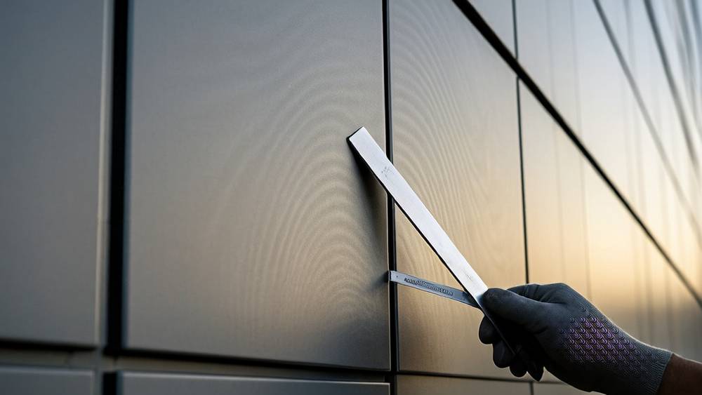
The first question most project managers ask when specifying aluminium wall panels exterior cladding is not about colour or finish. It is about thickness. A 2.0 mm panel costs roughly 18% less than a 3.0 mm panel at the procurement stage, but that saving can evaporate the moment a loaded flatbed trailer pulls into the site and the foreman runs a straightedge across the first sheet. Flatness defects, particularly the visible undulation known as oil canning, are the single largest source of post-installation disputes between fabricators and general contractors on solid aluminium facade projects. Oil canning is not a material failure in the metallurgical sense, but it reads as one to the client who has just approved a $200,000 facade package and expects mirror-flat surfaces under every daylight condition. This article examines the relationship between panel thickness, stiffener design, alloy temper selection, and installation practice, and provides verifiable dimensional thresholds that separate acceptable waviness from actionable warp in aluminium wall panels exterior applications.
What Oil Canning Actually Is and What It Is Not
Oil canning describes a wavy distortion pattern in flat metal sheet that resembles the bottom of an old oil can. When light glances across the panel surface at grazing incidence, ideally in the early morning or late afternoon, the eye picks up alternating concave and convex bands. ASTM does not publish a standalone standard for oil canning, but the phenomenon is addressed indirectly in ASTM E1794 (Standard Specification for Adhesive for Bonding Foam Core Sandwich Panels) and referenced in AAMA 508 and 509 documents governing voluntary tolerances for metal panels used in wall cladding.
Three common misconceptions need clearing up immediately:
- Oil canning is not structural failure. A panel with visible oil canning retains its full load-bearing capacity, weathertightness, and coating integrity. The problem is aesthetic, but aesthetics drive 90% of cladding disputes.
- Oil canning is not caused by the coating. PVDF and FEVE finishes sit on top of the metal substrate and do not contribute to the elastic buckling that produces visible waviness.
- Oil canning is not always the fabricator's fault. Substrate flatness, handling during transport, framing alignment tolerances, and thermal movement all contribute. Blaming the fabricator alone misses the point.
The core mechanism is elastic buckling. When residual stresses introduced during the aluminium rolling process are not fully relieved, the sheet can buckle at stress levels well below the material's yield point. The visible amplitude of oil canning typically ranges from 0.5 mm to 3.0 mm across a 1.2 m span. Per AAMA 508-14, a panel is generally considered non-conforming when the deviation exceeds 3.0 mm over any 600 mm straightedge measurement, though project specifications often tighten this to 1.5 mm on high-end architectural work with aluminium wall panels exterior installations.
Panel Thickness and the Flatness Equation
The relationship between sheet thickness and oil canning resistance is not linear. Doubling the thickness does not halve the visible distortion; it reduces it by a factor governed by the panel's bending stiffness, which scales with the cube of thickness. A 3.0 mm solid aluminium panel is approximately 3.4 times stiffer than a 2.0 mm panel of the same alloy and width, because the section modulus calculation involves t³. That cubic relationship means the jump from 2.0 mm to 2.5 mm produces a meaningfully flatter panel in most site conditions, while the further jump to 3.0 mm pushes the panel into territory where oil canning becomes rare under normal framing spans.
The table below summarises the practical flatness behaviour observed across commonly specified solid aluminium panel thicknesses, based on panels measuring 1,200 mm wide with a 600 mm stiffener spacing and standard 3003-H14 alloy.
| Panel Thickness | Relative Bending Stiffness | Typical Oil Canning Amplitude | Risk Level (600 mm Span) | Recommended Stiffener Spacing |
|---|---|---|---|---|
| 2.0 mm | 1.0 (baseline) | 1.5 – 3.5 mm | High: requires strict handling protocol | ≤ 400 mm |
| 2.5 mm | 1.95 | 0.8 – 2.0 mm | Moderate: manageable with stiffeners | ≤ 500 mm |
| 3.0 mm | 3.38 | 0.3 – 1.0 mm | Low: rarely detectable under diffuse light | ≤ 600 mm |
| 4.0 mm | 8.0 | < 0.5 mm | Negligible for most wall applications | ≤ 700 mm |
These numbers come from field measurements on completed aluminium wall panels exterior projects across Southeast Asia and the Middle East, not from laboratory conditions. Real-world results degrade when panels are stored flat on uneven pallets, lifted with improper rigging, or fixed to out-of-tolerance subframes.
One critical detail that specification writers often overlook: the alloy and temper matter as much as the thickness. The most common grade for architectural solid aluminium panels is 3003-H14, which offers a yield strength of approximately 145 MPa and reasonable formability. Some fabricators, including Futeng®, offer 5052-H32 as an alternative when the project demands higher stiffness and better corrosion resistance. The 5052-H32 alloy delivers roughly 30% higher yield strength (193 MPa vs 145 MPa), which translates directly into improved oil canning resistance at the same thickness. On a 2.5 mm panel, switching from 3003-H14 to 5052-H32 can reduce visible waviness by an observable margin without increasing the material cost proportionally, because the price delta between the two alloys is typically under 10% at mill level.
Stiffener Geometry, Not Just Stiffener Presence
Adding stiffeners to the rear face of a solid aluminium panel is standard practice. What gets less attention is the cross-sectional geometry of those stiffeners. A hat-section stiffener with 25 mm flanges and a 30 mm web height provides roughly 2.4 times the bending resistance of a flat bar stiffener of equivalent mass, because the second moment of area is driven by the distance of material from the neutral axis. Fabricators who default to simple flat bar stiffeners to save on press brake setup time are leaving stiffness on the table.
The attachment method matters too. Stiffeners bonded with structural adhesive (two-part epoxy or polyurethane-based) distribute shear stress across the full contact area and avoid the localised stress concentration that mechanical fasteners introduce. Mechanical fastening, typically using stainless steel studs welded to the panel rear and nuts securing the stiffener, can create discrete points where the panel is pulled slightly toward the stiffener. Under grazing light, these attachment points can telegraph through to the visible face as subtle dimples. Adhesive bonding eliminates this risk but demands clean surface preparation and controlled curing conditions, which are harder to maintain in a high-volume fabrication shop.
The stiffener layout pattern should also reflect the panel aspect ratio. A panel measuring 1,200 mm wide by 3,000 mm tall with stiffeners running only vertically will exhibit different oil canning behaviour from one where horizontal stiffeners are added at third-points. The worst-case scenario, seen on several disputed projects, is a large-format aluminium wall panels exterior sheet with stiffeners oriented parallel to the long dimension only. This leaves the short axis unsupported and creates a pronounced cylindrical curvature visible from 20 metres away.
Thermal Movement and the Framing Interface
Aluminium expands at approximately 2.4 mm per metre per 100°C temperature rise. On a 3-metre panel subjected to a 60°C surface temperature swing between a cold winter night and direct summer sun, the total thermal movement reaches roughly 4.3 mm. If the panel is fixed rigidly at all four corners, that movement has nowhere to go except into elastic buckling of the panel face.
The correct detail uses fixed points at one end and sliding clips at the opposite end. The sliding connection must permit movement in the plane of the panel without introducing out-of-plane restraint. A poorly detailed sliding clip that jams under load is functionally equivalent to a fixed connection and defeats the purpose. On-site, installers sometimes overtighten fasteners on sliding clips because the visual appearance of a loose-looking connection triggers their instinct to "fix it properly." Clear installation drawings and a morning toolbox talk specifically addressing thermal movement detailing can prevent this.
Framing alignment is the other half of the interface problem. The flatness of the installed aluminium wall panels exterior system can never exceed the flatness of the substrate it is fixed to. If the steel or aluminium subframe is installed with a ±5 mm tolerance across a 3-metre bay, the cladding will follow that undulation regardless of how flat the individual panels were when they left the factory. A realistic subframe tolerance is ±2 mm over any 3-metre length, measured with a taut wire or laser. Achieving this requires the subframe installer to use shims at every bracket connection and to verify alignment before panels arrive on site.
Transport, Handling, and Site Storage
A panel that leaves the fabrication shop dead flat can arrive on site with oil canning already baked in. The culprit is almost always the way panels are stacked and transported. Solid aluminium panels should be stacked vertically on A-frame stillages with padded contact points, never laid flat on a truck bed where road vibration transmits directly into the panel face. Panels stored flat on site, especially on uneven ground with timber dunnage at wide spacings, can develop permanent set over just a few days as their own weight and temperature cycles induce creep.
The handling protocol for aluminium wall panels exterior packages should specify:
- Minimum two-person lift for panels exceeding 1.5 m² face area.
- Suction cup lifters for panels larger than 2.0 m², to avoid edge bending.
- Vertical storage on purpose-built stillages with neoprene padding at contact points.
- Inspection of each panel under oblique lighting before installation, with non-conforming panels flagged and set aside for assessment.
On one large-scale project in the Gulf region, the contractor reported a 12% rejection rate on 2.0 mm panels after transport from the fabricator 600 km away. After switching to 2.5 mm panels with the same transport method, the rejection rate dropped to under 3%. The cost of the thicker material was offset by the elimination of rework, resequencing delays, and the administrative burden of non-conformance reports.
Specifying Flatness Acceptance Criteria That Work
A specification that says "panels shall be free from oil canning" is unenforceable. Every metal panel exhibits some degree of waviness under the right lighting conditions. The enforceable specification quantifies what is acceptable and under what measurement conditions.
A workable flatness specification for aluminium wall panels exterior should reference a defined measurement protocol and a numerical threshold. The following criteria, adapted from AAMA 508 and refined through practical project experience, provide a starting point:
"When inspected from a distance of 3 metres under diffuse daylight conditions (not direct sunlight at grazing incidence), any deviation from a true plane exceeding 2.0 mm over any 600 mm straightedge measurement placed anywhere on the panel face shall be cause for rejection. Inspection shall be performed with panels installed in their final position."
The key phrase here is "diffuse daylight conditions." Specifying inspection under overcast sky or indirect light prevents the argument that every panel looks wavy when the sun is at a 5-degree angle. The 3-metre viewing distance is also important: it simulates the typical distance from which a building facade is viewed by occupants and passers-by. Oil canning visible only at 500 mm with a spotlight is not a real-world defect.
For premium architectural work, particularly on high-visibility facades such as podium levels, entrance canopies, and feature walls, tightening the threshold to 1.5 mm over 600 mm is common. This tighter tolerance effectively mandates 3.0 mm minimum panel thickness and 5052-H32 alloy, because 2.0 mm 3003-H14 panels will struggle to meet it consistently in production volumes.
When Oil Canning Is Inevitable and What to Do About It
Certain panel geometries make some degree of oil canning mathematically unavoidable. Very large panels with high aspect ratios (width-to-thickness ratios exceeding 400:1), panels with large un-stiffened central fields, and panels installed as rainscreen elements with minimal rear support all push the limits of what flat sheet metal can achieve. In these cases, three design strategies can mitigate the visual impact:
First, specify a non-specular finish. A low-gloss PVDF coating (gloss units below 25 at 60° measurement angle) scatters reflected light and makes oil canning far less visible than a high-gloss finish. The same panel with 15 GU and 60 GU finishes will look dramatically different under the same lighting conditions. Second, introduce intentional break lines or reveals into the panel layout. A panel divided into smaller visual fields by a 10 mm shadow gap reads as intentionally articulated rather than wavy. Third, use perforated panels where the programme allows. Perforation relieves some of the residual stress and the pattern itself breaks up the specular reflection that makes oil canning visible.
The table below compares the visual impact of oil canning across different surface finish types for aluminium wall panels exterior applications, based on field observations:
| Finish Type | Gloss Level (60° GU) | Oil Canning Visibility | Recommended Panel Thickness | Best Mitigation Strategy |
|---|---|---|---|---|
| High-gloss PVDF (solid colour) | 60 – 85 | Very high: visible under most conditions | 3.0 mm minimum | Stiffener spacing ≤ 400 mm, 5052-H32 alloy |
| Mid-gloss PVDF (solid colour) | 25 – 45 | Moderate: visible under direct sun | 2.5 mm minimum | Hat-section stiffeners, sliding clip system |
| Matte PVDF (solid colour) | 10 – 20 | Low: rarely objectionable | 2.0 mm acceptable with care | Adhesive-bonded stiffeners, vertical storage |
| Metallic / Mica PVDF | 30 – 55 | High: flake orientation amplifies waves | 3.0 mm recommended | Smaller panel modules, avoid large unbroken fields |
| Anodised (architectural Class I) | Variable (substrate-driven) | Moderate to high | 3.0 mm minimum | Etched or satin finish preferred over bright dip |
Inspection Protocol Before the Scaffolding Comes Down
The inspection window matters. Oil canning cannot be reliably assessed under artificial lighting inside a fabrication shop, and it cannot be assessed from 50 metres away with the naked eye. The protocol that has gained traction on well-run aluminium wall panels exterior projects follows a three-step sequence:
- Factory inspection: Check panel flatness on a calibrated granite surface table under controlled diffuse lighting. Reject panels exceeding 1.0 mm deviation over 600 mm at this stage, because site conditions will only make things worse.
- Mock-up inspection: Install a representative sample of panels on the actual subframe system under site conditions. Assess flatness at 3 metres distance under morning, midday, and late afternoon light. This is the only way to verify that the full system, panels plus framing plus fixings, performs as expected.
- In-situ inspection after installation: Conduct a walk-around with the architect, contractor, and fabricator representative. Use a 600 mm straightedge and feeler gauge on panels flagged by visual inspection. Document results panel by panel on marked-up elevation drawings.
This protocol costs roughly half a day of coordinated time on site and can prevent months of post-completion dispute. The mock-up stage is particularly valuable because it sets expectations. Once the architect has signed off on the mock-up under real lighting conditions, subsequent claims that the installed facade is "too wavy" can be objectively benchmarked against the approved sample.
Cost Implications of Flatness-Driven Specification Choices
Specifying 3.0 mm 5052-H32 panels with hat-section adhesive-bonded stiffeners instead of 2.0 mm 3003-H14 panels with flat bar mechanically fastened stiffeners adds approximately 35–45% to the material cost of the cladding package. On a 2,000 m² facade, that translates to an additional $45,000–$65,000 at typical solid aluminium pricing. That number looks large until it is set against the cost of removing and replacing 200 panels after the client rejects the facade, which can easily exceed $150,000 when access equipment, labour, material re-supply, and programme delay are accounted for.
The smarter approach is to differentiate by facade zone. Specify the premium system on the podium, entrance, and feature walls where viewing distances are short and architectural scrutiny is highest. Use the standard system on upper floors, rear elevations, and areas screened by landscaping. This tiered approach delivers the flatness where it matters without blowing the budget on elevations that nobody will ever inspect from closer than 20 metres.
Procurement managers should also note that the cost of aluminium wall panels exterior flatness is not just in the panel itself. It is distributed across the subframe tolerance specification, the transport and handling protocol, the installer training, and the inspection regime. A project that spends an extra 8% on the panel specification but saves 15% on defect rectification is a net winner, but only if the specification decisions are made at the design stage rather than during the post-installation dispute.