Why 3 mm Solid Aluminium Rainscreen Panels Outlast 2 mm Under CWCT Cyclic Wind Loads
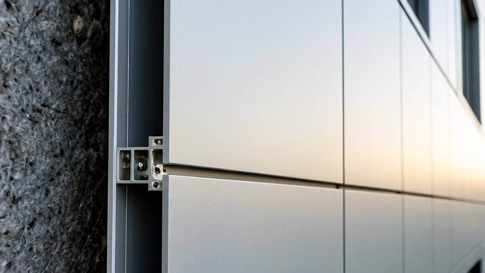
Rainscreen assemblies now dominate the conversation around facade wall cladding, but specifying the right aluminium panel gauge for a drained-and-ventilated cavity system involves far more than picking a thickness off a chart. Wind suction across a ventilated cavity behaves differently than it does on a face-sealed barrier wall. The cavity pressure equalisation that makes rainscreens so effective at moisture management also introduces a structural nuance that many project teams overlook: the outer skin carries a reduced net pressure, but the load cycling is more frequent and the panel perimeter fixation points experience concentrated stress that standard span tables rarely capture. Getting the gauge wrong on a facade wall cladding rainscreen means oil canning, fastener fatigue, or worse — panels that flutter audibly in moderate wind. This article walks through the engineering logic that connects cavity depth, clip design, wind zone, and aluminium panel thickness in rainscreen applications, with reference to ASTM E330 and CWCT standards.
Why a Rainscreen Cavity Changes the Structural Game for Aluminium Panels
A face-sealed wall relies on a single barrier to stop water, and wind pressure acts directly on the cladding surface with no backpressure relief. A rainscreen flips that logic. The outer cladding layer is deliberately open — at joints, at base and head flashings, at window perimeters — so that the air pressure in the cavity partially equalises with exterior wind pressure. This means the net structural load on the aluminium panel itself is lower than what the same panel would experience in a barrier wall at the same wind speed. But the catch is that this pressure equalisation is never perfect. Wind gusts create a lag between cavity pressure and exterior pressure, and that lag generates brief but repeating differential loads across the panel face.
For solid aluminium panels — typically supplied in 2.0 mm, 2.5 mm, and 3.0 mm gauges — this dynamic means deflection under intermittent suction becomes the governing limit state, not ultimate strength. A 2.0 mm panel might survive a single ASTM E330 proof load without permanent deformation yet still deflect enough under cyclic cavity pressure fluctuations to cause visible waviness after two years of service. The Centre for Window and Cladding Technology (CWCT) in the UK addresses this directly in their Standard for Systemised Building Envelopes, which recommends that rainscreen panel deflection under serviceability wind loads be limited to L/90 for aluminium panels — tighter than the L/60 sometimes used for barrier wall cladding. For a 1200 mm panel span between support rails, that means allowable mid-span deflection drops from 20 mm to roughly 13 mm. A 2.0 mm gauge panel that met the looser criterion might fail the tighter one.
Panel Gauge Selection Tied to Cavity Depth and Clip Standoff
One of the least-discussed variables in rainscreen panel engineering is the relationship between cavity depth and effective panel span. A 50 mm cavity requires short standoff clips that keep the panel close to the backup wall. But many projects now specify 100 mm to 150 mm cavities — driven by thicker continuous insulation layers or by the need to accommodate sub-girt systems for alignment on uneven substrates. A deeper cavity means longer clip standoffs, which means a longer moment arm between the panel attachment point and the structural backup. That longer arm amplifies the prying forces on fasteners under wind suction.
Consider a typical extruded aluminium support rail system fixed to vertical steel helping-hand brackets. With a 50 mm cavity, the clip standoff might be 65 mm from backup wall to panel back. With a 150 mm cavity, that standoff grows to 165 mm. The bending moment at the bracket-to-wall connection increases by a factor of roughly 2.5 for the same suction load. The panel gauge itself does not change the clip design, but thicker panels — 3.0 mm instead of 2.0 mm — distribute fastener loads over a wider bearing area at the rivet or screw head, reducing localised stress around the hole. This becomes critical in high-wind coastal zones where suction pressures can exceed 3.0 kPa under ASCE 7 design wind speeds.
Futeng® has observed that for projects in typhoon-prone Southeast Asian coastal cities, specifiers increasingly default to 3.0 mm solid aluminium panels with reinforced clip engagement zones — not because 2.5 mm cannot handle the design pressure, but because the thicker gauge reduces long-term fatigue risk at the clip-panel interface where stress concentrations are highest.
Wind Loads on Rainscreen Panels: What ASTM E330 and CWCT Actually Require
ASTM E330 — Standard Test Method for Structural Performance of Exterior Windows, Doors, Skylights and Curtain Walls by Uniform Static Air Pressure Difference — is the default reference in North American specifications for rainscreen panel structural testing. The test applies a static pressure differential, held for 10 seconds at design load and then ramped to 150% of design load. For a rainscreen panel, the specimen must be tested with the cavity condition representative of the installed configuration. That means the test chamber must replicate the cavity ventilation openings, because a sealed test (which would generate full pressure differential across the panel) overestimates the actual in-service load.
CWCT takes a different approach. Their Sequence B test for rainscreen systems applies 50 cycles of positive and negative pressure at serviceability load before the ultimate load test, specifically to evaluate fatigue performance of fixings and panel connections. This cycling requirement catches problems that a single ASTM E330 static pull might miss: fastener loosening, panel edge deformation at clip points, and gasket compression set in systems that use EPDM washers at rivet heads. A 2.0 mm aluminium panel with 4.8 mm diameter blind rivets at 300 mm centres might pass ASTM E330 but fail CWCT Sequence B because the rivet holes elongate slightly during cycling, introducing permanent panel play.
The table below summarises how panel gauge interacts with fastener type and spacing under these two test regimes, based on a 1200 mm × 600 mm panel module with four-side support:
| Panel Gauge | Fastener Type | Fastener Spacing | ASTM E330 (Static) | CWCT Sequence B (Cyclic) | Recommended Wind Zone |
|---|---|---|---|---|---|
| 2.0 mm | 4.8 mm Ø blind rivet, Al/SS | 350 mm centres | Pass up to 2.0 kPa | Marginal above 1.5 kPa | Low-rise, inland, sheltered |
| 2.5 mm | 4.8 mm Ø blind rivet, Al/SS | 300 mm centres | Pass up to 3.0 kPa | Pass up to 2.2 kPa | Mid-rise, suburban, moderate exposure |
| 3.0 mm | 5.5 mm Ø blind rivet, SS/SS | 250 mm centres | Pass up to 4.5 kPa | Pass up to 3.5 kPa | High-rise, coastal, typhoon/hurricane zones |
| 3.0 mm + stiffener | 5.5 mm Ø blind rivet, SS/SS | 200 mm centres | Pass above 5.0 kPa | Pass up to 4.5 kPa | Extreme exposure, 40+ storeys |
These numbers are indicative and assume 6063-T6 extruded aluminium support rails at 600 mm vertical centres. Specific project values must be confirmed by a qualified facade engineer with reference to local wind load codes: ASCE 7 in the United States, EN 1991-1-4 in Europe, AS/NZS 1170.2 in Australia and New Zealand, and GB 50009 in China.
The Fastener Problem Nobody Talks About: Galvanic Corrosion at the Clip
Solid aluminium panels in rainscreen applications almost always use aluminium support rails and aluminium clips. But fasteners introduce a material junction that sits inside the ventilated cavity — exposed to condensation, driven rain that penetrates the open joints, and in coastal environments, airborne chloride. A stainless steel blind rivet in an aluminium panel hole creates a galvanic couple. The aluminium is anodic to the stainless steel; under persistent moisture, the aluminium around the rivet hole corrodes preferentially.
The standard fix is to specify stainless steel rivets with an EPDM or nylon sealing washer that isolates the rivet body from the aluminium panel. But this isolation is never perfect. Installation tolerances, thermal cycling, and wind-induced panel movement gradually compromise the washer. For projects within 5 km of a marine coastline or in industrial zones with SO₂ exposure, some specifications now call for aluminium blind rivets with aluminium mandrels — accepting a lower shear strength in exchange for eliminating the galvanic couple entirely. A 5.5 mm aluminium rivet provides roughly 60% of the shear capacity of an equivalent-diameter stainless steel rivet, so fastener spacing must be tightened accordingly, which increases fabrication cost. This trade-off between corrosion resistance and structural efficiency is one that facade wall cladding specifiers in the Middle East and Southeast Asia increasingly face.
Cavity Ventilation Design and Its Effect on Panel Loading
Rainscreen cavity ventilation is not just about drying — it directly affects the pressure equalisation ratio that determines net panel load. The ventilation area (open joints at panel perimeters, dedicated vents at head and base) relative to the cavity volume sets how quickly the cavity pressure can track exterior wind pressure. A cavity with 500 mm² of ventilation opening per square metre of wall area equalises faster than one with 200 mm²/m². Faster equalisation means lower peak differential pressure across the panel — good for structural design. But larger openings also mean more water ingress during wind-driven rain, which demands a more robust drainage strategy at the cavity base.
CWCT recommends a minimum 50 mm cavity depth and ventilation openings equivalent to at least 500 mm² per linear metre at both the top and bottom of the cavity. For solid aluminium panels with open joints of 8–12 mm (typical for a drained-and-ventilated rainscreen aesthetic), the joint width itself often provides sufficient ventilation area without additional dedicated vents. A 1200 mm wide panel with 10 mm open joints on all four sides delivers roughly 44,000 mm² of ventilation per panel — far exceeding the CWCT minimum on a per-square-metre basis. However, when panels are installed with closed horizontal joints (a common aesthetic choice for horizontal-stripe facades), ventilation drops sharply and must be supplemented by discrete vents at cavity heads and bases. The structural implication: closed-joint rainscreens experience higher differential pressures and should be designed with panel gauge selected for the less-equalised pressure scenario — effectively treating the panel as if it were in a partially pressure-equalised cavity with a 0.3 to 0.5 pressure equalisation factor rather than the 0.7 to 0.9 factor achievable with fully open joints.
Thermal Movement in Rainscreen Panels: Gauge Matters More Than You Think
Aluminium expands at roughly 0.024 mm per metre per degree Celsius. A 3.0-metre-tall solid aluminium panel subjected to a 60°C surface temperature swing (from -10°C winter night to +50°C summer solar exposure) will expand and contract by approximately 4.3 mm over its length. Panel gauge influences how that movement manifests. A 2.0 mm panel, being more flexible, tends to accommodate thermal strain through slight out-of-plane bowing — which can present as oil canning on hot days. A 3.0 mm panel is stiffer and resists bowing, so the thermal strain concentrates at the fixed and sliding clip points. If the clip system does not provide adequate sliding capacity, the panel buckles at the fixed point or the fastener holes elongate.
Most rainscreen clip systems for solid aluminium panels use a combination of fixed points (typically two per panel near the top) and sliding points that allow vertical movement through slotted holes. The slot length must accommodate the full thermal movement range plus installation tolerance. For a 3.0-metre panel, a slot length of 10–12 mm at each sliding clip is common. Undersized slots are a frequent root cause of panel buckling complaints — and the problem is worse with thicker panels because they generate higher buckling resistance, which transfers more force into the connection rather than dissipating it through panel flexure.
The American Architectural Manufacturers Association (AAMA) publishes technical guidance on thermal movement accommodation in metal wall panels. Their TIR-A9 document, while focused on storefront and curtain wall, contains joint design principles that apply directly to rainscreen panel clip engineering.
Acoustic Considerations: When Rainscreen Panels Become Noise Sources
A facade wall cladding rainscreen that rattles in the wind is a warranty claim waiting to happen. The problem typically originates at the clip-panel interface. Wind gusts excite the panel at its natural frequency, and any looseness at the clip — whether from installation tolerance, thermal cycling, or fastener relaxation — translates into audible noise. Thicker panels (3.0 mm) have a higher natural frequency and greater mass, making them less susceptible to wind-induced vibration than 2.0 mm panels. But mass alone does not solve the problem. The clip design must include some form of positive engagement that prevents panel lift-off under suction while also damping vibration — typically a spring-loaded or wedge-lock clip that maintains contact pressure even as the panel moves thermally.
For projects near airports, rail corridors, or elevated highways, the acoustic performance of the entire rainscreen assembly becomes a specification line item. Solid aluminium panels themselves provide limited sound transmission loss — roughly 20–25 dB for a 2.5 mm panel depending on frequency — but the cavity behind them, when lined with mineral wool insulation, creates a mass-spring-mass system that can achieve STC ratings of 45–50 when properly detailed with acoustic breaks at floor lines. The panel gauge contributes to the outer mass in this system; increasing from 2.0 mm to 3.0 mm adds roughly 2.7 kg/m² of mass, which shifts the mass-spring-mass resonance frequency downward and improves low-frequency transmission loss.
Fire Performance of Solid Aluminium Rainscreen Systems
Solid aluminium panels are non-combustible — classified as A1 or A2-s1,d0 under EN 13501-1 depending on the coating system. This makes them inherently suitable for buildings above 18 metres in England (post-Grenfell regulatory environment) and for Type I and Type II construction under the International Building Code. But the panel is only one component. The full rainscreen assembly — including insulation, support rails, clips, vapour barrier, and cavity fire barriers — must also meet the required fire classification. A non-combustible aluminium panel mounted on combustible phenolic resin clips or over PIR foam insulation negates the benefit of the aluminium face material.
Open-state cavity fire barriers — typically mineral wool with intumescent strips that expand to seal the cavity at floor lines — are now mandatory in many jurisdictions for rainscreens over 18 metres. These barriers interrupt the cavity ventilation path, which means the pressure equalisation behaviour of the cavity changes near floor lines. Panels immediately above and below fire barriers experience localised pressure differentials that differ from panels in the mid-floor zone. Specifiers should request that the rainscreen engineer model these edge effects and confirm that panel gauge and clip spacing remain adequate in the barrier-adjacent zones.
Fabrication Tolerances and Their Impact on Installed Panel Performance
Solid aluminium panels for rainscreen applications are typically fabricated by CNC routing and folding from flat sheet, or by assembling a perimeter frame with a face sheet bonded or welded in place. The latter method — cassette-style fabrication — allows larger panel sizes (up to 1500 mm × 4000 mm in 3.0 mm gauge) but introduces flatness challenges. A 3.0 mm face sheet that is perfectly flat when it leaves the fabricator can develop subtle pillowing between perimeter stiffeners once installed, particularly on south-facing elevations where solar gain drives surface temperatures above 70°C.
Tighter fabrication tolerances reduce this risk but increase cost. A panel flatness tolerance of ±1.0 mm per 600 mm (roughly 0.17% of span) is achievable with CNC-folded panels from premium fabricators. Relaxing to ±2.0 mm per 600 mm saves fabrication cost but increases the probability of visible waviness under raking light — a common source of post-installation disputes between architects and contractors. This is where gauge selection intersects with commercial reality: a 3.0 mm panel can tolerate slightly larger flatness deviations before they become visually objectionable, because the thicker material reflects light differently and the eye is less sensitive to gradual curvature than to the sharper pillowing that thinner panels exhibit.
Cost Implications of Gauge Selection in Rainscreen Projects
Material cost for solid aluminium sheet scales roughly linearly with thickness. Moving from 2.0 mm to 3.0 mm increases raw material cost by approximately 50%, but the material component is only part of the installed system cost. The table below breaks down the relative cost impact across a typical mid-rise rainscreen project:
| Cost Component | 2.0 mm Panel System | 2.5 mm Panel System | 3.0 mm Panel System |
|---|---|---|---|
| Aluminium sheet (raw) | Baseline | +22–25% | +45–50% |
| Fabrication (cut, fold, route) | Baseline | +8–12% | +15–20% |
| PVDF coating (3-coat, both sides) | Baseline | +3–5% | +5–8% |
| Support rails and clips | Baseline (lighter clips) | +10–15% (heavier clips) | +20–30% (reinforced clips) |
| Installation labour | Baseline | +5–8% | +10–15% |
| Total installed system cost | Baseline | +12–18% | +25–35% |
The cost premium for thicker gauge must be weighed against the long-term risks it mitigates: fewer warranty claims, reduced oil canning, lower maintenance, and compliance with stricter cyclic test standards. For a 20-storey commercial building with 8,000 m² of facade wall cladding, the difference between 2.0 mm and 3.0 mm might represent $200,000–$350,000 in additional system cost — significant, but small relative to the total curtain wall budget and dwarfed by the cost of a single cladding failure remediation after handover.
Specifying Rainscreen Panel Gauge: A Practical Decision Sequence
Given the interacting variables — wind zone, cavity depth, panel dimensions, fastener type, thermal range, acoustic requirements, fire strategy, and budget — selecting the right aluminium panel gauge for a rainscreen is not a single-decision problem. The following sequence reflects how experienced facade engineers approach it:
- Determine design wind pressure (positive and negative) per the governing code (ASCE 7, EN 1991-1-4, etc.) for the specific building location, height, and exposure category.
- Estimate pressure equalisation factor based on cavity ventilation design. Open-joint rainscreens: 0.6–0.9. Closed-joint with discrete vents: 0.3–0.6. Multiply design pressure by (1 – equalisation factor) to get net panel load.
- Calculate required panel section modulus to limit deflection to L/90 under net serviceability load. This determines the minimum gauge for a given panel span and support arrangement.
- Check fastener capacity at the panel-to-clip connection under net ultimate load (including the 1.5× safety factor per ASTM E330). Adjust fastener diameter, spacing, or panel gauge as needed.
- Verify thermal movement accommodation. Confirm that clip slot lengths are adequate for the panel's expected temperature range and gauge-dependent stiffness.
- Confirm fire strategy alignment. Ensure panel gauge is compatible with cavity fire barrier detailing and that the full assembly meets the required EN 13501-1 or ASTM E84 classification.
- Review cost delta and risk. If the cost to upgrade from 2.5 mm to 3.0 mm is under 15% of the rainscreen package and the project is in a high-wind or coastal zone, the thicker gauge is almost always justified.
This sequence aligns with the structural testing requirements of ASTM E330 and the system testing protocols of CWCT, both of which should be referenced explicitly in project specifications for rainscreen facade wall cladding.
For contractors and specifiers evaluating supply options, manufacturers with dedicated rainscreen engineering support — such as Futeng® — can provide panel gauge calculations referenced to project-specific wind loads and cavity configurations. The key is to request this analysis during the design development phase, not after the support rail layout has been fixed, because rail spacing and panel gauge are interdependent variables that must be optimised together. A project that locks in rail centres at 600 mm based on a 2.0 mm panel assumption may find that upgrading to 3.0 mm later in the process does not fully resolve deflection issues because the rail spacing — not the panel gauge — is the binding constraint.
Solid aluminium rainscreen panels perform when the gauge, the clip, the cavity, and the ventilation openings are engineered as one system. Treating panel thickness as an isolated checkbox on a material schedule invites exactly the kind of post-occupancy problems — fluttering, oil canning, fastener fatigue — that give rainscreens an undeserved reputation for being temperamental. The engineering exists. The standards exist. The data exists. What remains is the discipline to apply them in the right sequence, with the right test references, before the first panel leaves the fabrication shop.