Slotted Fasteners Stop Oil Canning in Metal Facade Panel Systems
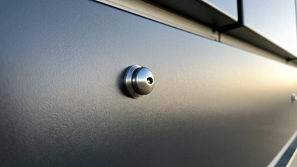
When a general contractor asked us why their 3.0 mm solid aluminium metal facade panel installation developed visible rippling across a south-facing elevation only six months after handover, the answer was not in the material thickness. It was in the fixing system. Solid aluminium cladding panels in the 2.5 mm to 3.0 mm range carry enough inherent rigidity to span 600 mm to 900 mm between supports without deflection issues, yet the same panels can warp noticeably when the substructure fails to accommodate one simple physical reality: aluminium expands and contracts roughly 2.4 mm per linear metre across a 100°C surface temperature swing. Most project teams understand this in theory. Fewer translate it into fastener specification, slot geometry, and installation sequencing. This article examines what actually happens at the fixing point when a metal facade panel heats up on a July afternoon, why standardised expansion calculations often miss real-world conditions, and how to specify fasteners and sub-frame connections that keep the facade flat across decades of thermal cycling.
The Numbers Behind Thermal Movement Nobody Checks
The coefficient of linear thermal expansion for aluminium alloy 3003 and 5052 — the two grades most commonly specified for solid metal facade panel fabrication — sits at approximately 23.8 × 10⁻⁶ per °C. For a 3,000 mm long panel, a temperature delta of 80°C (from -20°C overnight in a northern climate to +60°C surface temperature under direct summer sun) produces 5.7 mm of linear growth. That number surprises many specifiers who have been using 2 mm per metre as a rule of thumb without checking the underlying assumptions.
The error compounds when the substructure material differs from the panel material. A galvanised steel sub-frame expands at roughly 12.0 × 10⁻⁶ per °C — about half the rate of aluminium. When both materials heat up together, the aluminium panel attempts to grow nearly twice as much as the steel rail supporting it. Differential movement between panel and sub-frame introduces shear forces at every fixing point, and those forces concentrate at the fastener head.
ASTM E228 sets the standard test method for linear thermal expansion of solid materials, and any reputable metal facade panel supplier should provide expansion data traceable to this standard rather than quoting generic textbook values.
Fixed Point vs Sliding Point: Why Most Subcontractors Get This Wrong
Every metal facade panel on a building needs exactly one fixed point — a fastener location where the panel is locked in both horizontal axes, preventing it from migrating across the elevation over repeated thermal cycles. All other fasteners must function as sliding points, allowing the panel to grow and shrink freely in at least one direction. This principle sounds straightforward. On site, it gets compromised routinely.
The most common failure mode observed across dozens of project reviews: installers tighten every rivet or screw to the same torque across the entire panel, effectively creating multiple fixed points. When the panel heats up, each fastener resists movement. The panel cannot expand in-plane, so it buckles out-of-plane instead. The resulting oil-canning is not a material defect — it is a restraint problem.
Correct detailing places the fixed point at the panel's geometric centre or at one upper corner, depending on the system design. Rivets at all other locations should sit in slotted holes oriented parallel to the expected expansion direction. For a vertically oriented panel, horizontal slots allow vertical growth; for a horizontally oriented spandrel panel, vertical slots allow horizontal growth. Slot length must exceed the calculated movement by a safety factor of at least 1.5.
| Panel Length (mm) | Calculated Movement at Δ80°C (mm) | Minimum Slot Length with 1.5x Safety Factor (mm) | Common Site Error |
|---|---|---|---|
| 1,500 | 2.85 | 4.3 | Using standard 3 mm round hole instead of slot |
| 2,000 | 3.80 | 5.7 | Rivet overtightening restricting slot travel |
| 3,000 | 5.70 | 8.6 | No slot at all — round holes throughout |
| 4,000 | 7.60 | 11.4 | Slot orientation perpendicular to expansion axis |
| 4,500 | 8.55 | 12.8 | Slot too short; panel binds at temperature extremes |
Fastener Selection: The Gap Between Catalogue Ratings and Facade Reality
Structural engineers sizing fasteners for metal facade panel systems typically check wind load resistance — pull-out, pull-over, and shear capacity against the project's design wind pressure. Thermal cycling adds a fatigue dimension that static wind load calculations ignore. A panel on a south-facing elevation in a temperate climate might undergo 30 to 50 full thermal cycles per year where the surface temperature swings from near-freezing to over 50°C inside a single day. Over a 30-year design life, that is 900 to 1,500 cycles of 5 mm to 8 mm movement at each sliding fastener.
Stainless steel blind rivets with a 4.8 mm or 6.4 mm diameter dominate solid aluminium panel fixing. The mandrel material matters: aluminium mandrel rivets expand and contract at rates closer to the panel itself, reducing galvanic corrosion risk but offering lower shear strength. Steel mandrel rivets provide higher clamping force but introduce a dissimilar metal junction that requires isolation, typically through a nylon or EPDM sleeve at each fastener hole.
A widely referenced resource is AAMA's TIR-A9 design guide for metal cladding attachment, which lays out fastener fatigue considerations that go beyond simple static capacity tables. The guide notes that cyclic thermal loading should be treated as a serviceability limit state, not just an ultimate limit state.
Rivet vs Screw: A Thermal Performance Comparison
The choice between blind rivets and self-tapping screws for metal facade panel attachment has thermal implications that go beyond installation speed. Rivets, once set, maintain consistent clamping force regardless of thermal cycling because the mandrel locks the rivet body in compression. Self-tapping screws, particularly those driven into aluminium sub-frames without thread-locking compound, can back out incrementally over hundreds of thermal cycles. A screw that loses even 0.2 mm of preload creates enough clearance for panel chatter in wind, and the resulting noise travels through the substructure into occupied spaces.
Where screws are unavoidable — for example, on systems designed for panel-level demountability — specifying screws with an integrated nylon patch or applying a measured dose of thread-locking adhesive at installation is not optional. The additional cost runs approximately £0.08 to £0.15 per fixing point, which on a project with 8,000 fasteners adds roughly £1,000 to the total budget. Compared to the cost of re-cladding even one elevation that develops widespread fastener loosening, the arithmetic favours the patch screw.
Sub-Frame Design: Steel, Aluminium, or the Hybrid That Causes Problems
The substructure supporting metal facade panel systems typically uses either hot-dip galvanised steel or extruded aluminium. Steel sub-frames cost less per linear metre and offer higher stiffness for a given section depth, making them the default choice on mid-rise commercial projects where the primary constraint is budget rather than weight. Aluminium sub-frames dominate on high-rise work where dead load reduction matters and on projects near marine environments where galvanised steel's zinc layer faces accelerated consumption.
The thermal incompatibility between aluminium panels and steel sub-frames creates a design problem that many standard system drawings gloss over. When a 3,000 mm aluminium panel fixed to a steel rail heats up, the panel wants to grow roughly 3.4 mm more than the steel rail beneath it. If all fasteners sit in round holes, the panel cannot move relative to the rail, and the resulting compressive stress in the aluminium can exceed 40 MPa — enough to initiate buckling in a 2.5 mm thick panel with a 900 mm stiffener spacing.
A hybrid approach using aluminium panel clips mounted on steel rails decouples the thermal movement problem. The clip, typically a 2.0 mm thick aluminium extrusion 60 mm to 80 mm long, fastens rigidly to the steel rail through a single round hole. The panel then attaches to the clip through slotted holes that permit movement. Because the clip and panel share the same thermal expansion coefficient, the only differential movement occurs at the clip-to-rail connection, and this single point can be designed as the fixed point for that panel segment.
Futeng® has supplied solid aluminium panels for projects where this clip-on-rail approach eliminated oil-canning complaints that had plagued earlier phases built with direct panel-to-steel fixing. The clip design added approximately 6% to the material cost but reduced the call-back rate on thermal-related facade issues to near zero across three subsequent phases.
Temperature Mapping: Why Ambient Air Temperature Data Is Misleading
Specifiers who pull design temperatures from ASHRAE climate data for the project city are using the wrong numbers. Ambient air temperature and metal facade panel surface temperature diverge significantly under solar radiation. A dark-coloured aluminium panel with a PVDF coating in RAL 7016 (anthracite grey) can reach 75°C to 82°C on a day when the air temperature is only 32°C. The same panel in a light metallic silver (RAL 9006) might peak at 50°C to 55°C under identical conditions.
The Lawrence Berkeley National Laboratory's Heat Island Group research provides solar reflectance data for various coating colours and materials. A high-reflectance PVDF coating with a total solar reflectance (TSR) of 0.65 or above can reduce peak panel temperature by 15°C to 20°C compared to a standard coating with a TSR of 0.35. That temperature reduction translates directly to 0.7 mm to 1.0 mm less expansion per 3,000 mm panel length — enough to bring borderline slot designs back within safe limits.
Project teams specifying dark-coloured metal facade panel systems should perform a solar temperature calculation rather than relying on air temperature extremes. The calculation involves the panel's solar absorptance (a function of coating colour and formulation), the site's peak solar irradiance (available from local meteorological records), and the panel's convective heat transfer coefficient (driven by wind exposure and panel orientation). A south-facing panel in still air will run hotter than a north-facing panel in a breezy location, and the expansion calculations should reflect these differences zone by zone.
Stiffener Integration and Thermal Stress Distribution
Solid aluminium panels in the 2.5 mm to 3.0 mm thickness range typically require stiffeners — aluminium extrusions or folded profiles bonded or welded to the panel rear face — to meet deflection limits under wind load. These stiffeners span between the main fixing rails and transfer wind pressure from the panel skin to the substructure. They also create thermal bridges within the panel assembly.
The standard practice of continuously welding stiffener ends to the panel perimeter frame introduces a thermal restraint condition that many fabricators do not analyse. A 2,500 mm long stiffener welded at both ends to the panel's return leg experiences the same 5.7 mm growth as the panel skin when heated. If the stiffener section is a 40 mm × 20 mm × 2 mm aluminium channel, its cross-sectional area of roughly 160 mm² generates approximately 2.2 kN of compressive force against each weld when fully restrained — enough to distort the panel edge if the return leg is only 20 mm deep.
Three fabrication approaches reduce this risk:
- Intermittent welding along the stiffener length, leaving unwelded gaps that act as expansion joints within the panel assembly
- Slip-fit stiffener connections where the stiffener end slides into a bracket rather than being rigidly welded, allowing independent thermal movement
- Structural adhesive bonding using two-part epoxy or polyurethane adhesives that provide enough shear strength for wind load transfer while permitting micro-movement through the adhesive layer's viscoelastic behaviour
The ISO 15614 standard for welding procedure qualification applies to aluminium panel fabrication and should be referenced when specifying weld quality for stiffener attachment. Poor weld penetration combined with thermal fatigue is a common root cause of stiffener detachment in panels that have survived multiple seasonal cycles.
Case Comparisons: What Goes Wrong When Thermal Detailing Fails
Project A: 18-Storey Residential Tower, Manchester UK
The south and west elevations featured 2.5 mm solid aluminium metal facade panel systems in a dark bronze PVDF finish. Within two years of completion, residents on upper floors reported tapping and creaking noises from the facade during early morning hours as the sun hit the elevation. Investigation revealed that all panel fasteners had been installed in round holes with no provision for sliding movement. The panels, restrained on all four edges, were buckling outward by up to 4 mm and snapping back as temperatures fluctuated. Remediation involved removing every panel, slotting the fixing holes, and reinstalling with sliding clips — at a cost exceeding the original cladding subcontract value.
Project B: Airport Terminal Extension, Middle East
The design specified 3.0 mm solid aluminium panels spanning up to 1,200 mm between horizontal rails, with panel lengths reaching 4,200 mm. The project's thermal analysis used air temperature data (0°C to 48°C) rather than surface temperature data. Actual panel surface temperatures measured on the south elevation reached 92°C in August. The resulting 9.2 mm of expansion exceeded the 6 mm slots specified. Panels at mid-height on the elevation showed edge binding and permanent deformation at corners. The fix required replacing the longest panels with shorter modules and increasing slot lengths to 14 mm.
These two cases illustrate the same root cause approached from different angles: thermal movement calculations that used incomplete inputs. The Manchester project had correct temperature data but omitted slot detailing. The Middle East project had slots but used the wrong temperature range.
Specification Checklist for Thermal Movement Accommodation
A metal facade panel specification that adequately addresses thermal movement should include the following elements, ideally in the performance section rather than buried in installation notes:
- Design temperature range: State the panel surface temperature range used for movement calculations, not the ambient air range. Reference the specific coating colour and solar absorptance value.
- Movement calculation method: Reference the linear thermal expansion coefficient for the specific aluminium alloy (3003, 5052, or equivalent) per ASTM E228.
- Fixed point location: Define which fastener position serves as the fixed point for each panel and require it to be clearly marked on shop drawings.
- Sliding fastener specification: Detail slot dimensions with the calculated safety factor, slot orientation relative to panel axes, and fastener type with torque limits for sliding connections.
- Sub-frame compatibility: Where panel and sub-frame materials differ, require a differential movement analysis and specify isolation details at each connection point.
- Stiffener attachment method: Specify whether stiffeners are continuously welded, intermittently welded, or adhesively bonded, and require thermal stress verification for the chosen method.
- Mock-up testing: Require a visual inspection of the installed mock-up after exposure to a full day of solar heating, with panels checked for flatness deviation before sunrise and again at peak afternoon temperature.
The Centre for Window and Cladding Technology (CWCT) in the UK publishes guidance on thermal movement in cladding systems that provides a useful framework for developing project-specific movement calculations. Their methodology for mapping surface temperatures to coating solar absorptance values is particularly relevant for dark-coloured metal facade panel specifications.
Installation Sequencing and Seasonal Effects
Even a perfectly detailed thermal movement system can fail if panels are installed at an ambient temperature near one extreme of the design range. A panel fixed in place during winter at -5°C and detailed with slots oriented for expansion will use most of its slot travel just reaching the neutral position when summer arrives. If the slot length was calculated from a mid-range installation temperature assumption, the actual movement available in the expansion direction may be insufficient.
Best practice requires the installation contractor to record the ambient temperature at time of fixing and adjust the fixed-point position within the slot accordingly. For panels installed in cold conditions, the fastener should sit toward the expansion end of the slot, reserving maximum travel for the growth direction. For panels installed in hot conditions, the fastener should sit toward the contraction end. This adjustment is simple in concept but rarely executed on site without explicit instruction in the method statement.
The thermal movement challenge in solid aluminium metal facade panel systems is not a materials science problem — the physics has been understood for decades. It is a coordination problem between the specifier who calculates movement at a desk, the fabricator who cuts slots on a factory floor, and the installer who tightens fasteners on a scaffold. Closing that coordination gap with clear specification language, shop drawing annotation, and site inspection checkpoints costs almost nothing and prevents the kind of systematic facade failures that damage reputations long after the project team has moved on to the next job.