Vertical Aluminium Fins Why 6061 T6 Excels Over 6063 T5 at 6 Metre Spans
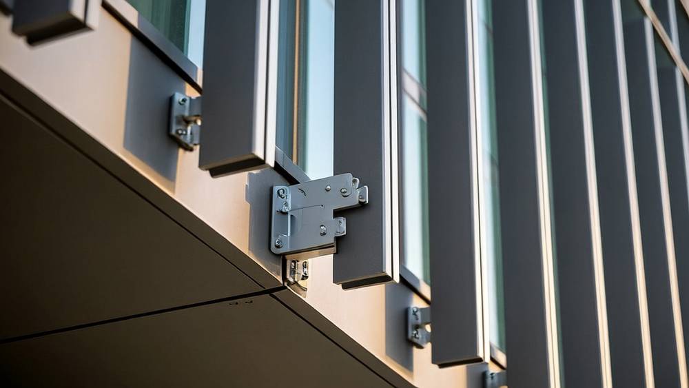
Specifying vertical aluminium fins for a commercial façade goes far beyond picking a profile shape and a powder coat colour. The detail that separates a 15-year trouble-free installation from one riddled with alignment drift, fastener corrosion, and water ingress at year five is the connection between fin and primary structure. Most project teams spend weeks debating fin depth, spacing, and alloy grade, then default to a generic bracket detail pulled from a curtain wall supplier's standard library. That shortcut is precisely where failures begin.
This article examines vertical aluminium fins through the lens of bracket engineering and attachment methodology. We focus on three connection types that dominate global specification: face-fixed cleat brackets, thermally broken through-bolt systems, and slotted adjustable carriers. Each carries distinct load-path characteristics, thermal movement accommodation, and on-site tolerance absorption. The analysis draws on ASTM E330 structural performance testing, AAMA TIR-A9 thermal bridge guidance, and real-world installation data from projects across Southeast Asia, the Middle East, and North America. If you are a façade engineer, procurement manager, or building envelope contractor wrestling with a specification that demands fins spanning 6 metres with zero visible fixings, the following sections address the problem at the bracket level — where it belongs.
The Bracket Problem Nobody Discusses During Design Development
Vertical aluminium fins behave as cantilevered beams. Wind load pushes against the fin face, generating bending moments that concentrate at the attachment point. A 150 mm deep fin spanning 4.2 metres floor-to-floor in a 2.0 kPa wind zone transfers roughly 3.8 kN·m of moment into the bracket assembly. That number matters because most off-the-shelf aluminium cleats rated for curtain wall transoms are designed around 1.2 to 1.8 kN·m.
The failure mode is rarely catastrophic collapse. What happens instead is cumulative: the bracket yields microscopically during each storm event, the fin rotates 2-3 mm out of plane, and within 18 months the façade reads as visibly wavy when viewed from street level. Rectifying this on a 30-storey tower requires scaffold access, fin removal, bracket replacement, and re-coating of the aluminium — costs that routinely exceed the original fin package value by 300%.
Three root causes recur across projects we have reviewed:
- Bracket material mismatch: Specifying 6063-T5 aluminium brackets for fins carrying high moment loads when 6061-T6 or stainless steel 316 would be appropriate. The yield strength difference — 145 MPa versus 276 MPa — doubles the bracket's load capacity for the same geometry.
- Inadequate thermal movement provision: A 6-metre vertical aluminium fin experiences approximately 8-10 mm of linear expansion from a 50°C temperature swing. Rigid two-bolt connections at each support prevent this movement, forcing the fin to bow between restraint points.
- On-site tolerance absorption: Primary structure deviations of ±15 mm are common on cast-in-place concrete frames. Brackets that offer no slotted adjustment force installers to shim connections with improvised packing, introducing stress concentrations and galvanic contact points.
Addressing these issues starts with selecting the correct connection topology for the project's specific conditions. The three dominant types are examined below with engineering data and application guidance.
Connection Type 1: Face-Fixed Cleat Brackets
Face-fixed cleats are the most widely specified bracket for vertical aluminium fins on low-to-mid-rise projects. A typical assembly consists of an L-shaped aluminium or stainless steel angle with one leg bolted to the slab edge or curtain wall mullion and the other leg fastened to the rear face of the fin using two or three M8 or M10 bolts.
Structural Characteristics
The cleat functions as a short cantilever, and its capacity is governed by three parameters: material yield strength, section modulus of the vertical leg, and bolt shear capacity at the fin interface. For a 6061-T6 aluminium cleat with a 100 mm vertical leg and 8 mm thickness, the moment capacity at yield is approximately 2.1 kN·m per bracket. This supports a 150 mm × 50 mm fin up to roughly 3.5 metres span in a 1.5 kPa wind zone, assuming brackets spaced at 1.2-metre centres.
Face-fixed cleats leave visible bolt heads on the fin face unless a secondary cover plate or snap-on capping is specified. This aesthetic consideration drives many projects toward concealed systems, but the structural simplicity of face-fixed connections provides a reliability advantage: installers can visually verify bolt tightness and bracket alignment during installation and throughout the building's service life.
Thermal Performance
Standard aluminium cleats create a direct thermal bridge from the exterior fin to the interior structural slab. In cold climates, this path can drop the internal surface temperature at the connection point below dew point, causing condensation and eventual mould growth on interior finishes. The AAMA TIR-A9 document provides calculation methods for assessing this risk. Where the project requires compliance with ASHRAE 90.1 or local energy codes, face-fixed cleats should be paired with a thermal break pad — typically a 10 mm thick FRP (fibre-reinforced polymer) shim placed between the cleat and the slab edge.
A simple decision rule: if the project's heating degree days exceed 3,000, budget for thermally broken connections from the schematic design phase. Retrofitting thermal breaks after brackets are fabricated adds 40-60% to the bracket cost and 3-4 weeks to the procurement schedule.
Cost and Procurement
Face-fixed cleats are the lowest-cost option among the three connection types. Budget figures from 2024-2025 Southeast Asian and Middle Eastern supply chains place fabricated 6061-T6 cleats at USD 8-15 per bracket for quantities above 500 units, including PVDF coating to match the fin finish. Stainless steel 316 cleats run USD 22-35 per bracket. Lead times range from 4-6 weeks for aluminium and 6-8 weeks for stainless, depending on casting versus machining requirements.
Connection Type 2: Thermally Broken Through-Bolt Systems
Through-bolt systems address the thermal bridging limitation of face-fixed cleats while providing higher moment capacity for deep fins and long spans. The assembly sandwiches the fin between a front pressure plate and a rear structural bracket, with bolts passing through the fin body. Thermal separation is achieved by isolating the exterior pressure plate from the interior bracket using polyamide struts or FRP isolators.
Engineering the Thermal Break
The thermal break material must satisfy two competing requirements: low thermal conductivity and high compressive strength. Polyamide 6.6 with 25% glass fibre reinforcement is the industry standard, offering thermal conductivity of 0.30 W/m·K versus 160 W/m·K for aluminium — a reduction factor of over 500. The compressive strength of reinforced polyamide at 2.5% strain is approximately 120 MPa, sufficient to transfer bolt preload without creep over a 25-year service life.
The structural penalty is real: introducing a thermal break reduces the assembly's effective section modulus by 15-25% compared to an all-aluminium connection of the same external dimensions. This must be accounted for in the structural calculation package submitted for building permit review. Projects following the ASTM E330 test protocol should require the bracket supplier to provide test reports for the complete thermally broken assembly, not just the aluminium components tested independently.
Concealed Aesthetics and Water Management
The through-bolt configuration places all fasteners behind the fin face, achieving the clean, uninterrupted vertical lines that architects specify for premium commercial towers. The trade-off is water management. Bolt penetrations through the fin body create potential leak paths, and the thermal break joint between pressure plate and rear bracket forms a capillary gap that draws water inward under wind-driven rain conditions.
Effective detailing requires three layers of defence: EPDM gaskets at each bolt penetration, a continuous silicone sealant bead along the pressure plate-to-fin interface, and a pressure-equalised cavity behind the fin that drains to the exterior at each floor level. Testing to ASTM E1105 (water penetration by uniform static air pressure difference) at 720 Pa is recommended for projects in hurricane-prone regions or locations with annual rainfall exceeding 1,500 mm.
Cost Comparison
Thermally broken through-bolt assemblies cost 2.5 to 3.5 times more than face-fixed cleats on a per-bracket basis. For a 20,000 m² façade with fins at 600 mm centres, the bracket package alone represents USD 180,000-250,000. This cost must be weighed against the long-term energy savings from eliminated thermal bridges and the avoided cost of condensation remediation. A lifecycle cost analysis using a 25-year net present value typically favours the thermally broken option for buildings in climate zones 4-8 (ASHRAE classification).
Connection Type 3: Slotted Adjustable Carrier Systems
Slotted adjustable carriers are the preferred solution for projects where primary structure tolerances are large and programme schedules do not permit extensive rectification of the concrete frame. These systems use a continuous aluminium carrier rail mounted to the slab edge with vertically slotted holes, into which individual fin brackets slide and lock at the required position.
Tolerance Absorption Mechanism
The key innovation is the decoupling of structural attachment from fin positioning. The carrier rail accommodates ±20 mm of horizontal adjustment and ±15 mm of vertical adjustment through slotted connections, while a secondary micro-adjustment mechanism at the bracket-to-fin interface handles ±5 mm in all three axes. This layered adjustment capability means the fin installation team can achieve ±2 mm alignment accuracy across a 30-metre façade run even when the underlying concrete edge varies by ±18 mm.
The cost of this flexibility is increased bracket assembly weight and complexity. A typical slotted carrier assembly weighs 4.5-6.0 kg per linear metre of façade, compared to 1.2-1.8 kg per bracket for a face-fixed cleat system. The additional dead load must be included in the building's structural model, particularly for high-seismic zones where the carrier rail mass contributes to the façade's inertial load during an earthquake.
Seismic Performance
Projects in seismic design categories D and E require vertical aluminium fins to accommodate inter-story drift without shedding components or losing load-bearing capacity. The NEHRP recommended seismic provisions for architectural components (Chapter 13 of ASCE 7) require façade elements to withstand a relative displacement of 1.5 times the design story drift.
Slotted carrier systems address this by permitting the fin to slide within the carrier during a seismic event, dissipating energy through friction rather than transferring it into brittle failure of the aluminium brackets. Testing at the NIST large-scale structural testing facility has demonstrated that properly detailed slotted connections can accommodate ±50 mm of relative displacement without loss of vertical load-carrying capacity.
Specifiers should require the bracket supplier to provide cyclic test data per AAMA 501.6 (recommended dynamic test method for determining the seismic drift causing glass fallout from a wall system) adapted for fin attachments. A minimum of three complete cycles at the design drift amplitude with no bracket deformation exceeding 0.2% residual strain is a reasonable acceptance criterion.
Material Selection for Brackets: Aluminium Grade and Corrosion Protection
Bracket material selection is governed by three factors: structural demand, environmental exposure, and galvanic compatibility with the fin alloy and fasteners. The table below summarises the key engineering properties of the four bracket materials most commonly specified for vertical aluminium fins.
| Material | Yield Strength (MPa) | Thermal Conductivity (W/m·K) | Corrosion Class (ISO 12944) | Relative Cost Factor | Typical Application |
|---|---|---|---|---|---|
| 6063-T5 Aluminium | 145 | 200 | C2-C3 | 1.0 | Low-rise, inland, low wind |
| 6061-T6 Aluminium | 276 | 167 | C2-C4 | 1.4 | Mid/high-rise, moderate wind |
| Stainless Steel 304 | 215 | 16.2 | C3-C4 | 2.5 | Coastal, high humidity |
| Stainless Steel 316 | 290 | 16.2 | C5-I, C5-M | 3.6 | Marine, chemical plant, de-icing salt exposure |
A critical detail often overlooked: when stainless steel brackets connect to aluminium fins, a physical isolation barrier is mandatory. Without it, the galvanic potential between 316 stainless steel and 6063-T5 aluminium in the presence of an electrolyte (rainwater, condensation) drives corrosion of the aluminium at a rate of 0.05-0.10 mm per year in marine environments. A 1 mm thick EPDM or neoprene isolation pad between the bracket and fin eliminates the galvanic cell and extends the connection's service life to match the 25-30 year design life of the PVDF coating system.
Bracket Spacing Optimisation: Balancing Cost and Performance
Bracket spacing directly drives the total installed cost of vertical aluminium fins. Reducing the spacing from 1.5 metres to 1.0 metres increases the bracket count by 50% — on a 15,000 m² façade, that translates to roughly 3,000 additional brackets and USD 45,000-75,000 in incremental material cost alone, before installation labour.
The optimisation problem is constrained by three limits:
- Deflection limit: Typically L/175 for aluminium façade components under wind load, where L is the span between brackets. A 150 mm deep fin at 1.5-metre bracket spacing deflects approximately 8.6 mm under 1.5 kPa wind load, which is within the L/175 limit of 8.6 mm — right at the boundary.
- Stress limit: Maximum bending stress must remain below 0.6 × yield strength for the fin alloy under the project's design wind pressure with a 1.5 safety factor applied per ASCE 7 load combinations.
- Resonance avoidance: The natural frequency of the fin between supports must exceed 5 Hz to prevent wind-induced vortex shedding excitation. Fin sections deeper than 200 mm with bracket spacing above 1.8 metres can drop below this threshold, particularly for fins fabricated from 3003-H14 alloy which has a lower modulus-to-density ratio than 6063-T5.
For most commercial projects using 150-200 mm deep fins in 6063-T5 or 6060-T6 alloy, the optimal bracket spacing falls between 1.2 and 1.5 metres. Projects in wind zones exceeding 2.5 kPa design pressure should reduce spacing to 1.0 metre and consider upgrading bracket material from 6063-T5 to 6061-T6.
Installation Sequencing and Quality Control
Bracket installation tolerances set the upper limit on achievable fin alignment. A bracket positioned 3 mm out of plane at the slab edge translates to a 12 mm deviation at the fin tip of a 400 mm deep fin — a 3:1 amplification due to the cantilever geometry. This amplification effect means bracket installation accuracy must be roughly four times tighter than the specified fin alignment tolerance.
Recommended quality control protocol:
- Pre-installation survey: Laser-scan the slab edge at 300 mm intervals along the entire façade line. Generate a deviation map identifying zones where the concrete edge exceeds ±10 mm from design position. These zones require bracket packers or custom shim plates fabricated before the installation crew mobilises.
- Bracket setting: Use a total station or robotic layout tool to mark each bracket position to ±2 mm in all three axes. Do not rely on string lines for buildings over 20 metres in height — wind deflection of the string line alone introduces ±5 mm of error.
- Post-installation verification: Survey every bracket position before fin installation begins. Any bracket exceeding ±3 mm deviation must be corrected. This is the single most cost-effective quality intervention in the entire vertical aluminium fins installation sequence — catching a bracket error at this stage costs minutes; catching it after fins are installed costs days.
For large-scale projects, Futeng® has supplied vertical aluminium fins with pre-assembled bracket sub-components that reduce on-site bracket setting time by approximately 40% compared to traditional piece-by-piece assembly. The key is integrating the bracket, thermal break, and primary fasteners into a single factory-assembled unit that arrives on site with certified torque settings and documented material traceability.
Procurement Strategy: Separating Fin and Bracket Packages
A procurement approach that consistently produces better outcomes is to separate the fin fabrication package from the bracket supply package, even when both are sourced from the same manufacturer. This creates transparency in cost breakdown and allows the structural engineer to specify bracket performance criteria independently of the fin supplier's standard catalogue.
The bracket specification should include as minimum requirements:
- Material grade and temper with mill test certificates per EN 10204 Type 3.1
- Moment capacity at yield and at 1.5× design load (tested, not calculated)
- Thermal conductivity of any thermal break component with ISO 8301 test data
- Coating system specification matched to the fin coating (same PVDF resin system, same applicator where possible)
- Adjustment range in all three axes with tolerance stack-up analysis
- Galvanic isolation details and isolation material specification
Requesting these items in the tender package signals to bidders that the connection detail is being treated as an engineered component, not an afterthought. Suppliers who cannot provide structural test data for their standard brackets are unlikely to deliver components that meet the project's performance requirements.
Lessons from Three Completed Projects
Project A: 28-storey commercial tower, Dubai, UAE. Vertical aluminium fins spanning 3.8 metres, 200 mm depth, bracket spacing 1.3 metres. Original specification called for face-fixed 6063-T5 cleats. During submittal review, the façade consultant upgraded to 6061-T6 thermally broken through-bolt assemblies after wind tunnel testing revealed localised pressure coefficients 40% higher than the code-calculated values. The bracket cost increased by USD 85,000 but eliminated a predicted 12 mm deflection at corner zones that would have required remedial work within the defects liability period. Post-completion laser survey confirmed fin alignment within 3 mm across the entire façade.
Project B: 12-storey hospital, Singapore. Slotted adjustable carriers specified from tender stage due to known concrete tolerance issues with the main contractor's previous projects. The carrier system absorbed slab edge deviations of up to 22 mm without requiring any bracket packers. Installation productivity averaged 28 linear metres of fins per crew per day, compared to 18 metres on a comparable project using fixed brackets with on-site shimming. The 55% productivity gain offset the higher carrier system material cost within the first six floors of installation.
Project C: 6-storey university building, Toronto, Canada. Face-fixed stainless steel 316 cleats specified for a vertical aluminium fins installation on a building with extensive winter de-icing salt exposure from adjacent roadways. The project team initially questioned the 3.6× cost premium over aluminium brackets. Within three years, a neighbouring building using aluminium brackets in the same exposure zone exhibited visible white corrosion product and pitting at bracket-to-fin interfaces. The university project's brackets showed no corrosion after six winters of service.
These cases reinforce a consistent pattern: bracket engineering decisions made during design development have a disproportionate impact on the long-term performance of vertical aluminium fins. The bracket is not a commodity item to be value-engineered out of the budget. It is the single component that determines whether the fin system performs for 5 years or 25.