Why 1.5 mm Plat Perforated Aluminium Facade Panels Buckle Under Wind Suction
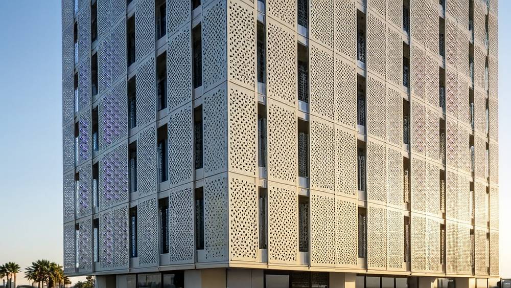
In 2023, a 22-storey mixed-use tower in Kuala Lumpur replaced its entire east-facing facade after just four years of service. The culprit was not structural failure or coating delamination — it was perforation collapse. The original 1.5 mm plat perforated aluminium panels, specified with a 23% open area and staggered round holes on 8 mm centres, had buckled inward under cyclic wind suction, permanently deforming the hole bridges and rendering the rain-screen non-functional. The post-mortem revealed a detail that every facade engineer, cladding contractor, and procurement manager should internalise: the 1.5 mm gauge left only 2.6 mm of solid metal between adjacent 5.4 mm perforations. At a span of 600 mm between fixing rails, that web width simply could not carry the negative pressure loads the building envelope was designed to withstand.
This failure — and dozens of similar cases across Southeast Asia, the Middle East, and coastal Australia — exposes a knowledge gap that runs through procurement specifications globally. Architects select perforated panels for solar shading, visual permeability, and ventilation performance. Specifiers reference ASTM and EN standards for the base aluminium alloy. Yet the mechanical integrity of the perforated sheet itself — the effective section modulus after punching, the stress concentration at hole edges, and the resulting deflection under wind load — often receives no independent engineering scrutiny at all. This article addresses that gap directly, with a focus on material gauge, open area ratio, span limits, and what actually governs whether a plat perforated aluminium facade panel will hold its geometry across a 25-year service life.
How Perforation Rewrites the Mechanical Rules of Aluminium Sheet
A solid 2.0 mm aluminium sheet spanning 600 mm between supports behaves predictably. Its section modulus can be calculated from the full rectangular cross-section, and deflection checks follow straightforward beam theory. Perforate that same sheet with 5 mm round holes at 8 mm staggered centres — yielding a 35% open area — and the mechanical model changes entirely. The remaining metal between holes, called the ligament or web, becomes the load path. At 35% open area on a staggered round pattern, the minimum ligament width drops to approximately 3.0 mm. That narrow strip of 5000-series or 3000-series aluminium must now carry all the bending stress the full sheet width previously handled.
The effect on bending stiffness is dramatic. Research published by the Metal Construction Association indicates that a perforated plate with 30% open area typically retains only 50% to 60% of the bending stiffness of its solid counterpart, depending on hole pattern and pitch. At 40% open area, that figure can drop below 40%. This is not a linear relationship — stiffness degrades faster as open area increases because the remaining ligaments become both narrower and fewer in number. For plat perforated aluminium panels on building facades, where maximum deflection under design wind load is typically limited to span/175 or span/240 depending on the cladding system, this stiffness reduction must be explicitly accounted for in panel thickness selection, not assumed away by referencing the solid-sheet properties of the base alloy.
| Open Area Ratio | Hole Diameter (mm) | Staggered Pitch (mm) | Min. Ligament Width (mm) | Effective Bending Stiffness (% of Solid Sheet) | Recommended Minimum Gauge (mm) for 600 mm Span |
|---|---|---|---|---|---|
| 15% | 3.0 | 7.0 | 4.0 | 78–85% | 1.5 |
| 23% | 5.0 | 10.0 | 5.0 | 65–72% | 2.0 |
| 30% | 6.0 | 10.5 | 4.5 | 50–60% | 2.5 |
| 35% | 5.0 | 8.0 | 3.0 | 45–55% | 2.5 |
| 40% | 8.0 | 12.0 | 4.0 | 35–45% | 3.0 |
| 45% | 6.0 | 8.5 | 2.5 | 25–35% | 3.0 |
The data above represents conservative values derived from multiple projects where panels were tested to EN 1999-1-1 deflection limits. Ligament width below 3.0 mm at 35% open area and above should be treated as a red flag in specification review. The Kuala Lumpur failure sat precisely in this danger zone — 23% open area sounds moderate on paper, but the combination of 5.4 mm holes and tight 8 mm pitch produced a ligament too narrow to survive repeated suction cycling.
The Span-Gauge-Open Area Triangle That Governs Every Facade
Three variables interact to determine whether a plat perforated aluminium rainscreen panel will perform or fail: the unsupported span between fixing rails, the sheet gauge, and the open area percentage. Change one and you must re-evaluate the other two. A common procurement mistake involves a value-engineering exercise that reduces gauge from 2.5 mm to 2.0 mm while keeping the perforation pattern and span unchanged. The cost saving on material — perhaps 15% to 18% on the aluminium sheet — evaporates the first time the building faces a storm event at or near the design wind speed.
Consider a panel with 30% open area, 6 mm round holes on 10.5 mm staggered pitch. At 2.5 mm gauge with a 600 mm span, the effective section modulus after perforation can handle a design wind pressure of roughly 1.8 kPa (serviceability limit state). Drop to 2.0 mm gauge at the same span and open area, and the allowable pressure falls to approximately 1.1 kPa — a 39% reduction. If the building is in a region where AS/NZS 1170.2 or EN 1991-1-4 yields a design pressure of 1.5 kPa or higher, the 2.0 mm panel will deflect beyond serviceability limits, potentially disengaging from its fixing system or permanently deforming.
Manufacturers such as Futeng® have developed internal span-gauge matrices for perforated panels based on both laboratory testing and field monitoring across tropical cyclone zones. Their engineering teams routinely reject 1.5 mm gauge for any perforated facade panel with open area above 20% when the span exceeds 500 mm, regardless of what the architect's visual intent brief requests.
The interaction works in the opposite direction too. A project that genuinely needs 40% open area for ventilation or daylight transmission should expect to use 3.0 mm gauge and reduce span to 500 mm or less between supports. There is no lightweight perforated panel that delivers both high transparency and structural economy over long spans. The physics of aluminium does not permit it.
Stress Concentration at Hole Edges and the Fatigue Risk Nobody Calculates
Even when a perforated panel passes static deflection checks, a second failure mechanism lurks: fatigue cracking at hole edges under repeated wind loading. A solid aluminium sheet distributes bending stress relatively uniformly across its width. A perforated sheet concentrates stress around each hole perimeter, with peak stress occurring at the points tangent to the bending axis. For a round hole in a plate under bending, the stress concentration factor (Kt) typically ranges from 2.0 to 2.8 depending on hole spacing and sheet thickness, according to Peterson's Stress Concentration Factors data widely referenced in mechanical engineering.
This means the actual stress experienced at the hole edge can be nearly three times the nominal bending stress calculated from the reduced cross-section. Over thousands of wind cycles — a typical facade in a coastal city might experience 50,000 to 200,000 significant pressure cycles over 25 years — these concentrated stresses can initiate micro-cracks at the hole perimeter. Once a crack propagates across the narrow ligament to the adjacent hole, the panel loses structural continuity along that line, and the perforation pattern effectively becomes a tear path.
The risk is highest with punched perforations rather than laser-cut or waterjet-cut holes. Mechanical punching leaves a work-hardened edge zone with residual tensile stresses. Combined with the geometric stress concentration, punched holes in 5000-series alloys (particularly 5052-H32 and 5754-H22, the most common plat perforated aluminium grades) can exhibit reduced fatigue life compared to machined holes. Laser cutting produces a heat-affected zone with different metallurgical characteristics — generally softer at the edge — which can be either beneficial or detrimental depending on the alloy and the thermal history of the sheet. For facade applications in high-cycle fatigue environments (tall buildings in windy cities, coastal esplanade structures), specifying laser-cut or waterjet-cut perforations with a subsequent stress-relief treatment warrants serious consideration, even though it adds approximately 20% to 30% to the perforation processing cost.
Alloy Selection for Perforated Facade Panels Beyond the Data Sheet
The two aluminium alloy families that dominate perforated architectural panels are 3000-series (typically 3003-H14) and 5000-series (typically 5052-H32 or 5754-H22). The choice between them carries implications for perforation quality, post-punching flatness, and long-term dimensional stability that go well beyond the yield strength numbers on a mill certificate.
3003-H14 offers good formability and consistently clean punched hole edges. Its lower magnesium content (1.0–1.5% Mn as the primary alloying element) means less tendency for the punched edge to develop the rough, torn appearance that can plague higher-strength alloys. For perforated panels where hole-edge aesthetics matter — visible from close range in lobby facades or interior atrium screens — 3003 often produces a superior visual result straight off the punching press. The trade-off is lower strength: 3003-H14 has a typical tensile yield strength of 145 MPa versus 195 MPa for 5052-H32. That 26% strength deficit must be compensated by increased gauge, closer support spacing, or reduced open area.
5052-H32 and 5754-H22 provide the higher strength that allows thinner gauges and larger spans, but they demand more careful perforation process control. The magnesium content (2.2–2.8% for 5052, 2.6–3.6% for 5754) increases the alloy's work-hardening rate, which means the punched hole edge zone can become significantly harder and more brittle than the base metal. If the punching tool clearance is not optimised for the specific gauge and hole diameter, the result can be micro-cracking at the hole perimeter that is invisible to the naked eye but present from day one. These micro-cracks then serve as initiation points for the fatigue mechanism described above.
The alloy-grade decision also affects flatness after perforation — a parameter that matters enormously for facade panel aesthetics. Perforating a sheet releases residual stresses from the rolling process unevenly across the panel width. 3003, with its lower strength and lower work-hardening rate, typically exhibits less post-perforation distortion than 5052 at the same gauge and open area. Some plat perforated aluminium manufacturers apply a post-perforation stretcher-levelling pass to restore flatness tolerances within 0.5% of panel diagonal, but this step adds cost and lead time that should be factored into the procurement schedule.
Coating Systems and the Hole-Edge Corrosion Vulnerability
A solid aluminium rainscreen panel receives its PVDF or FEVE coating after fabrication, with the liquid or powder coating covering the face, returns, and edges in a continuous film. A perforated panel presents a fundamentally different coating challenge: every single hole creates an internal cylindrical surface that must be coated to prevent corrosion initiation. If the coating does not adequately cover the hole interior, moisture can wick into the aluminium substrate at the hole edge — precisely where the stress concentration is highest and where any fatigue micro-crack would start.
The industry standard for architectural aluminium coating, AAMA 2605, specifies performance requirements for the coating film but does not specifically address the challenges of coating perforated geometries. A panel with 30% open area and 6 mm holes spaced at 10.5 mm has roughly 1,900 mm of hole-edge perimeter per 100 mm × 100 mm of panel area. That is a substantial length of exposed aluminium if coating coverage is inadequate.
Two coating approaches exist for plat perforated aluminium. The first — coating the sheet after perforation — ensures that the hole interiors receive coating material, but the process can be uneven: electrostatic spray application tends to deposit more coating on the face surface than inside holes, and the hole edges may only receive a fraction of the nominal dry film thickness. The second approach — coating the solid sheet before perforation — guarantees uniform face coating but leaves the hole interiors as bare aluminium. For interior applications or sheltered locations, this may be acceptable. For exterior facades exposed to rain, salt spray, or industrial pollutants, post-perforation coating with a verified minimum dry film thickness of 25 microns inside the holes (tested on sacrificial samples from the same batch) should be specified in the coating submittal requirements.
Fixing Systems and the Problem of Reduced Bearing Area
Perforated panels attach to their support structure through mechanical fixings — typically aluminium clips, rivets, or bolts engaging with the panel returns or through fixings in the panel face. The presence of perforations reduces the available bearing area around each fixing point, which changes the pull-through resistance of the connection.
A typical solid aluminium cassette panel with a 20 mm return leg and a clip engaging every 400 mm has a well-understood fixing capacity based on the bearing strength of the aluminium and the clip geometry. When that same panel is perforated, a clip that happens to align with a hole location will have reduced edge distance and may not develop full bearing capacity. The solution is not simply to avoid placing fixings at hole locations — on a panel with 35% open area and 5 mm holes, the probability of a 10 mm wide clip landing fully on solid metal is lower than intuition suggests, especially if the clip position is fixed by the support rail spacing and cannot be adjusted to suit the hole pattern.
The practical approach involves one of two strategies: either design the perforation pattern to leave solid fixing lanes (unperforated strips at the clip attachment lines), or use a continuous aluminium profile at the panel edge that transfers the fixing loads independently of the perforated field. The first strategy constrains the architectural design but simplifies engineering verification. The second strategy adds a fabrication step — bonding or mechanically fastening a solid edge profile to the perforated sheet — and must account for galvanic compatibility if dissimilar aluminium alloys or stainless steel fasteners are involved. Both strategies cost more than simply perforating the full sheet and attaching clips wherever the rail spacing dictates, but both prevent the type of progressive fixing failure that starts with one loose clip and cascades across the panel under repeated wind loading.
Acoustic Performance as a Secondary Design Driver
While this article focuses on structural integrity, the acoustic implications of plat perforated aluminium panels deserve brief attention because they interact with the open-area and gauge decisions already discussed. Perforated panels function as part of a sound-absorbing facade system when combined with an acoustically absorptive backing layer — typically mineral wool or acoustic fleece behind the perforated skin. The sound absorption coefficient depends strongly on the open area ratio, hole diameter, sheet thickness, and the depth of the cavity behind the panel.
From an engineering specification standpoint, the key interaction is this: the open area required for acoustic performance (often 20% to 35% for meaningful absorption in the 500 Hz to 2000 Hz speech-frequency range) overlaps directly with the open-area range where structural performance degrades most rapidly. A specifier pursuing an NRC (Noise Reduction Coefficient) of 0.75 or higher with a perforated aluminium rainscreen will almost certainly need an open area above 25%. That pushes the panel design into the territory where 2.0 mm gauge becomes marginal and 2.5 mm or 3.0 mm becomes the structurally responsible choice. The acoustic consultant and the facade engineer must communicate on this point early in the design development phase; separating these decisions into disconnected work packages has produced some of the most expensive remedial facade works the industry has seen.
Quality Verification Protocols for Incoming Perforated Panels
Given the sensitivity of plat perforated aluminium panel performance to gauge, hole geometry, and flatness, the incoming inspection process on site should go beyond counting panels and checking surface finish. Three specific verification steps, drawn from EN 485 and ASTM B209M reference frameworks for aluminium sheet products, provide a practical quality gate:
- Gauge verification: Measure sheet thickness at a minimum of five points per panel — at each corner and at the centre — using a calibrated digital micrometer with 0.01 mm resolution. The tolerance for 2.0 mm nominal gauge per EN 485-3 is ±0.09 mm. Reject any panel where the average falls below the lower tolerance limit, as this directly reduces the already-diminished bending stiffness.
- Hole diameter and pitch check: Using a digital calliper or optical comparator, verify hole diameter and centre-to-centre pitch on a sample of holes from each panel. A hole diameter 0.3 mm larger than specified may seem trivial, but it increases open area, reduces ligament width, and was the precise failure contributor in the Kuala Lumpur case. The cumulative effect of oversized holes across a panel can shift open area by 2–3 percentage points.
- Flatness measurement: Place the panel on a calibrated granite surface plate or equivalent flat reference. Measure the maximum deviation from the reference plane using a dial indicator or feeler gauge. For a panel up to 1,200 mm × 2,400 mm, the flatness deviation should not exceed 0.5% of the diagonal length (approximately 13 mm). Panels exceeding this limit will be visibly wavy once installed and may not engage correctly with the fixing system.
These checks take approximately 10 minutes per panel for a trained inspector and should be performed on a statistically representative sample — typically the first five panels of each batch and then one per 20 thereafter, following the sampling logic of ISO 2859-1 for normal inspection level. The cost of this inspection is negligible compared to the cost of replacing an entire facade elevation.
The Kuala Lumpur tower that opened this article spent approximately 1.4 million USD on facade replacement, excluding the consequential costs of business interruption on the occupied floors and the professional fees for the forensic investigation. The gauge difference between the failed 1.5 mm panels and the 2.5 mm replacement panels represented a material cost delta of roughly 42,000 USD at the time of original procurement — about 3% of the eventual remediation cost. Engineering decisions made at the specification stage, when the perforation pattern is a visual concept and the gauge is a line item in a cost plan, carry consequences that compound across the life of the building. For plat perforated aluminium facade panels, getting the span-gauge-open area triangle right is not a detail to be value-engineered later. It is the detail that determines whether the facade performs for five years or for fifty.