Aluminium Clip In Ceiling Bevel Edge Panels Conceal Flatness Flaws
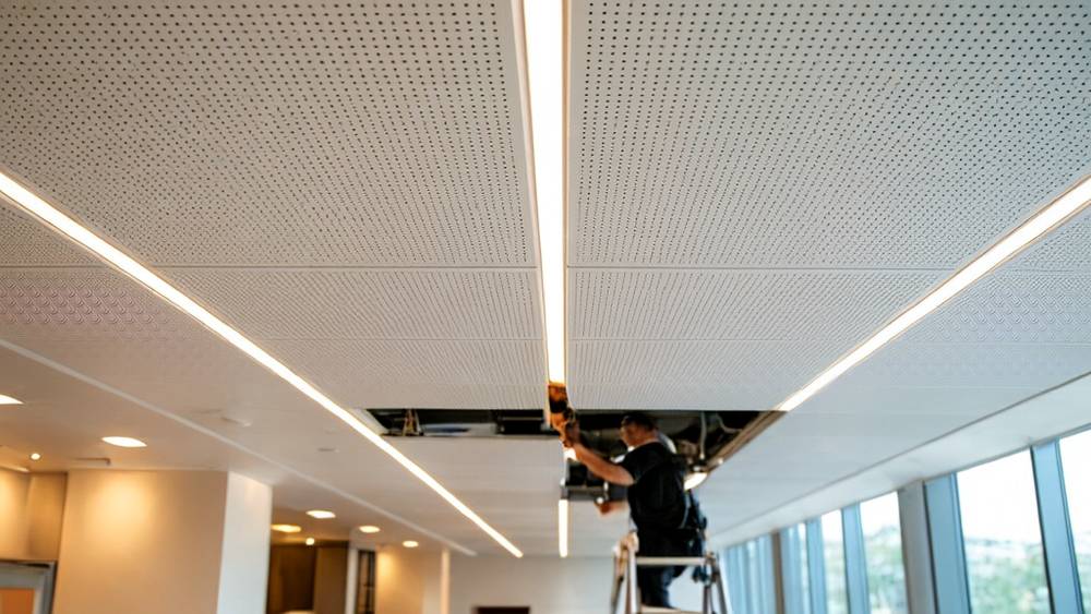
When a commercial project specifies a ceiling with zero visible grid lines, the specification almost always points to an aluminium clip in ceiling system. The appeal is obvious: a monolithic plane of metal with only hairline joints between panels. But the gap between a clean architectural drawing and a ceiling that actually stays flat, quiet, and accessible across a 10-year building lease is where most procurement decisions get tripped up. The single variable that determines whether a clip-in ceiling performs or disappoints is edge design — specifically, how the panel perimeter interfaces with the concealed keel. This article isolates that variable and examines how panel edge geometry drives on-site flatness, acoustic consistency, plenum access speed, and long-term maintenance cost across four common clip-in aluminium ceiling configurations.
The Edge Is the System: Why Panel-to-Keel Geometry Governs Everything
A clip-in aluminium ceiling is not a panel product. It is an interface product. The panel itself — typically 0.5 mm to 0.7 mm thick aluminium alloy (AA3003 or AA5005 series) with a polyester or PVDF coating — is structurally passive. All load transfer, alignment, and demountability depend on the formed edge profile where the panel clips onto the concealed carrier rail.
When a contractor complains that "the ceiling won't sit flat," the root cause is rarely the panel gauge. It is almost always edge profile mismatch: the clip geometry does not hold the panel in the correct Z-axis position under the combined weight of the panel itself plus any adhered acoustic fleece. Similarly, when a facilities team reports that removing a single panel for plenum access takes 15 minutes instead of 30 seconds, the edge design — not installer error — is the culprit.
Four edge types dominate the global aluminium clip in ceiling market. Each solves a different set of priorities, and each creates its own set of compromises:
- Bevel-edge clip (4.2 mm bevel): Creates a defined V-shaped joint line between panels. The bevel emphasizes individual tile geometry and masks minor panel-to-panel height discrepancies.
- Square-edge clip (zero bevel): Produces a near-invisible butt joint. Demands exceptional flatness tolerances because any deviation reads as a visible shadow line.
- Hook-and-spring clip: Uses a formed return leg with integrated spring tension. Prioritizes rapid demountability — often under 10 seconds per panel with a suction cup tool.
- Lock-and-key clip: Features a positive mechanical interlock requiring a specific release motion. Sacrifices access speed for vibration resistance in high-traffic or pressurized plenum zones.
Understanding these distinctions matters because procurement specifications in the Middle East, Southeast Asia, and European markets increasingly name specific edge profiles — not just "clip-in ceiling" — after experiencing failures where the wrong edge type was supplied against a generic performance spec.
Bevel-Edge Systems: The Specification Workhorse With a Visual Trade-Off
The 4.2 mm bevel-edge aluminium clip in ceiling panel, standardized by manufacturers including Genesis Materials and widely adopted across GCC commercial projects, remains the highest-volume configuration globally. The bevel serves two engineering functions that have little to do with aesthetics.
First, the angled edge creates a deliberate shadow gap that optically forgives ±1.5 mm of panel-to-panel height variation. On a 600 mm × 600 mm module installed across a 200-square-metre ceiling plane, achieving zero height variation across 556 individual panels is statistically improbable without laser-levelled carrier rails and millimetre-precision installation. The bevel absorbs that tolerance.
Second, the 4.2 mm dimension is not arbitrary. It corresponds to the minimum edge return required to form a stiffening flange on 0.6 mm aluminium sheet without cracking the material during roll-forming. Thinner material — attempted by some manufacturers to reduce cost — cannot hold a clean 4.2 mm bevel and will exhibit waviness along the joint line within weeks of installation.
However, the bevel introduces a real acoustic penalty. When perforated panels with acoustic fleece are specified, the V-groove creates a 4.2 mm-wide strip where sound absorption drops to near zero. Across a ceiling with 2 mm joint spacing (square-edge), the open joint area is approximately 0.33% of the total plane. With a 4.2 mm bevel, that number approaches 0.7% — doubling the acoustically "dead" area. For projects targeting NRC 0.85 or higher, this difference can mean the gap between specification compliance and test failure.
| Edge Type | Joint Visibility | Flatness Tolerance | Single-Panel Access Time | Acoustic Leakage (Open Area %) | Vibration Resistance |
|---|---|---|---|---|---|
| 4.2 mm Bevel | Visible V-groove | ±1.5 mm (forgiving) | 15–25 seconds | 0.65–0.72% | Moderate |
| Square (Zero Bevel) | Hairline butt joint | ±0.5 mm (demanding) | 18–30 seconds | 0.30–0.35% | Moderate |
| Hook-and-Spring | Hairline or micro-bevel | ±1.0 mm | 5–10 seconds | 0.30–0.50% | Low (spring fatigue risk) |
| Lock-and-Key | Near-invisible | ±0.5 mm | 30–60 seconds | 0.25–0.35% | High |
Square-Edge Clip Systems: When Architects Demand Invisible Joints
The square-edge aluminium clip in ceiling represents the aesthetic ceiling of what clip-in technology can deliver. Panels meet edge-to-edge with zero bevel, producing a joint line that can be as narrow as 1.5 mm. At ceiling height, these joints effectively disappear, creating the monolithic metal plane that architects specify for premium corporate lobbies, high-end retail, and museum interiors.
The engineering burden shifts entirely to the carrier system. With no bevel to mask deviation, the suspension grid must be levelled to within ±0.5 mm across any 3-metre span. This is achievable with laser-levelled, torsionally rigid main tees and cross tees — but it doubles the grid installation time compared to bevel-edge systems. Contractors who bid square-edge specifications without accounting for this labour multiplier routinely lose money on the ceiling package.
Thermal movement introduces another variable. An aluminium clip in ceiling panel measuring 600 mm × 1200 mm will expand by approximately 0.8 mm across its long axis when the plenum temperature rises from 18°C to 40°C (the range experienced when HVAC systems cycle in Middle Eastern or Southeast Asian buildings). In a bevel system, this expansion is absorbed within the V-groove. In a square-edge system, insufficient joint clearance creates panel-to-panel contact, generating an audible "ticking" sound as metal rubs against metal during thermal cycling.
The solution — specifying a minimum 2.0 mm joint gap and verifying that the clip mechanism allows longitudinal float — must be written into the specification before tender. Retrofitting this adjustment after installation requires dismantling the entire ceiling field.
Hook-and-Spring vs. Lock-and-Key: The Access Speed Equation
Above every aluminium clip in ceiling lies the plenum: a service cavity packed with ductwork, sprinkler piping, electrical conduit, and increasingly, IoT sensor networks and BMS wiring. The frequency with which maintenance teams need to access this space determines which clip mechanism makes economic sense.
Hook-and-spring systems use a formed stainless steel spring clip integrated into the panel edge. The installer pushes the panel upward until the spring compresses, then releases — the spring expands into a receiving groove on the carrier rail. Removal requires only a suction cup tool: pull down with approximately 3–5 kg of force, the spring compresses, and the panel releases. Cycle time: under 10 seconds per panel. Over 100 access events across a 5-year maintenance cycle, the time savings versus a lock-and-key system can exceed 40 labour hours.
The trade-off is spring fatigue. Stainless steel spring clips rated for 500+ cycles under ASTM testing conditions may degrade faster in environments with elevated humidity or airborne chlorides. A spring that loses tension will not hold the panel flush against the carrier, producing visible sagging at panel corners. For coastal installations or indoor swimming facilities, lock-and-key systems eliminate this failure mode by using a rigid mechanical interlock that does not rely on spring force for panel retention.
Lock-and-key clips demand a specific release motion — typically inserting a flat tool into the joint and rotating to disengage a tab. This motion is not intuitive; maintenance personnel must be trained, and turnover documentation must include clear removal instructions. In projects where the ceiling supplier is not responsible for post-occupancy training, lock-and-key systems generate service calls that could have been avoided with a simpler spring-clip design.
Facilities managers evaluating aluminium clip in ceiling systems should request cycle-test data for the specific spring mechanism proposed, not generic product literature. A reputable manufacturer — such as Futeng®, which supplies project-specific clip-in ceiling packages across Asia-Pacific and Middle Eastern markets — can provide third-party test reports documenting spring performance after accelerated aging cycles that simulate 10 years of operational use.
Acoustic Performance and Edge Design: The Fleece Adhesion Problem
Perforated aluminium clip in ceiling panels achieve their sound absorption rating through a layer of non-woven acoustic fleece bonded to the panel's rear surface. The fleece — typically black polyester or glass-fibre tissue weighing 30–60 g/m² — converts sound energy into heat through viscous friction as sound waves pass through the perforations.
Edge geometry directly affects fleece performance in two ways. First, the edge profile determines how close the fleece can be applied to the panel perimeter. On a bevel-edge panel, the fleece typically stops 3–5 mm short of the formed edge to prevent interference with the clip mechanism. This creates an untreated border zone where sound passes through perforations unimpeded, reducing the effective NRC by 0.05 to 0.10 compared to a panel where fleece extends to within 1 mm of the edge.
Second, the clip mechanism itself can compress or delaminate the fleece during panel insertion. Hook-and-spring systems that require the installer to push the panel upward with significant force can crush the fleece against the carrier rail, locally reducing its thickness and acoustic performance. Over multiple removal-and-reinstallation cycles — common during the commissioning phase when MEP contractors need repeated plenum access — this compression damage accumulates.
Specifiers should require a mock-up installation of at least six panels (2 × 3 grid) with acoustic fleece applied, followed by five removal-and-reinstallation cycles, before approving the clip-in system for full production. This mock-up reveals edge-related acoustic degradation that laboratory NRC tests on single panels will never capture. Industry guidance from organizations like the Ceiling & Interior Systems Association (CISA) and relevant ASTM E1414 testing standards reinforces the value of system-level acoustic verification rather than component-level ratings.
Plenum Access and Fire Strategy: Why Edge Design Changes Egress Planning
Building codes across jurisdictions — including the International Building Code (IBC), UAE Fire and Life Safety Code, and BS 9999 — treat the ceiling plane as part of the compartmentation strategy when it forms a barrier between occupied space and the plenum. An aluminium clip in ceiling with perforations and acoustic fleece can contribute to fire resistance only if the entire system — panels, clips, carrier grid, and suspension — is tested as an assembly under ASTM E119 or EN 1364-2.
Edge design matters here because fire testing evaluates whether panels remain in place during fire exposure. A lock-and-key clip mechanism that resists panel dislodgement under thermal deformation will maintain compartmentation longer than a spring-clip system where springs lose tension at elevated temperatures. This distinction becomes critical in healthcare facilities, data centres, and transportation hubs where ceiling integrity directly affects evacuation safety.
Additionally, the speed of plenum access affects firefighter operations. In a smoke-logged plenum, firefighters may need to remove ceiling panels to locate the fire source. A hook-and-spring aluminium clip in ceiling allows rapid panel removal without tools; a lock-and-key system requires a specific tool that may not be available during an incident. Some fire authorities now specify that designated panels along fire service access routes must use spring-clip mechanisms regardless of what the rest of the ceiling uses.
Procurement teams should request the full fire test assembly report — not just the material flame spread classification (ASTM E84 Class A or EN 13501-1 A2-s1,d0) — and verify that the test assembly matches the proposed edge configuration. A fire rating achieved with lock-and-key panels does not automatically apply to a spring-clip variant from the same manufacturer.
Material Thickness and Edge Formability: When Cost-Cutting Creates Callbacks
The global aluminium clip in ceiling market has seen downward pressure on panel thickness over the past five years as raw material costs have risen. Panels that were routinely specified at 0.7 mm are now commonly supplied at 0.5 mm, particularly on price-sensitive projects in South and Southeast Asia. This reduction has direct consequences for edge performance.
A 0.5 mm aluminium panel can be roll-formed into a clip edge, but the reduced material cross-section means the clip leg has lower bending stiffness. Under sustained load — the panel's own weight plus any adhered fleece, typically totalling 2.5–3.5 kg/m² — a 0.5 mm clip leg will creep over time, gradually relaxing its grip on the carrier rail. The result is a ceiling that looks perfect at handover and develops visible sagging at panel centres within 12–18 months.
The minimum recommended thickness for clip-in ceiling panels in commercial applications is 0.6 mm for modules up to 600 mm × 600 mm and 0.7 mm for larger formats or perforated panels where the open area reduces structural cross-section. These values align with recommendations from established manufacturers and are consistent with the performance requirements outlined in EN 13964 for suspended ceilings. Panels thinner than 0.6 mm may be acceptable for residential or light commercial use where plenum access frequency is low and visual flatness requirements are less stringent, but they should not be specified for public buildings, transportation facilities, or healthcare environments.
Verifying panel thickness on-site requires a micrometre — visual inspection is insufficient. A 0.5 mm panel with a thick coating can appear identical to a 0.6 mm panel. Procurement specifications should require mill certificates stating actual gauge, not nominal gauge, and should define the acceptable tolerance (typically ±0.03 mm per relevant ASTM or EN standards).
Specification Checklist: Matching Edge Type to Project Requirements
The following decision framework helps architects, specifiers, and procurement managers select the correct edge configuration for an aluminium clip in ceiling based on project-specific operational priorities rather than aesthetic preference alone:
- Define the plenum access frequency. If MEP maintenance requires panel removal more than twice per year in any zone, eliminate lock-and-key systems from that zone. The cumulative labour cost of slow access will exceed any material savings.
- Assess the flatness tolerance budget. If the ceiling is below 3.5 metres and illuminated by linear LED strips running parallel to panel joints (which cast shadows that highlight height discrepancies), budget for a laser-levelled grid and specify square-edge only if the installation contractor can demonstrate ±0.5 mm flatness capability.
- Calculate the acoustic impact of joint area. For spaces targeting NRC 0.80 or above, specify the minimum achievable joint width and verify that the acoustic consultant's model accounts for the open joint area specific to the chosen edge profile.
- Check fire test assembly documentation. Confirm that the fire test report matches the edge type, panel thickness, perforation pattern, and fleece specification proposed for the project. Do not accept a material-level reaction-to-fire classification as a substitute for system-level fire resistance testing.
- Verify coating compatibility with edge forming. Polyester coatings applied pre-forming can micro-crack at the bend radius of the clip leg. For exterior soffit applications exposed to humidity or coastal air, specify PVDF (minimum 70% Kynar 500® resin) and request evidence of post-forming coating integrity from bend-test samples.
- Require a multi-cycle mock-up. Before full production, install a minimum 2 m × 2 m ceiling section with all specified components — panels, carrier grid, acoustic fleece, perimeter trims — and cycle selected panels through five removal-and-reinstallation sequences. Inspect for clip deformation, fleece delamination, and joint alignment after each cycle.
Edge design is not a detail to be delegated to the ceiling subcontractor after the architectural specification is issued. It is the primary determinant of whether an aluminium clip in ceiling will meet the project's operational requirements across its entire service life. The panel is commodity aluminium. The edge is the engineering.