Solid Aluminium Sheet Cladding Thermal Movement Engineering for Long Life Facades
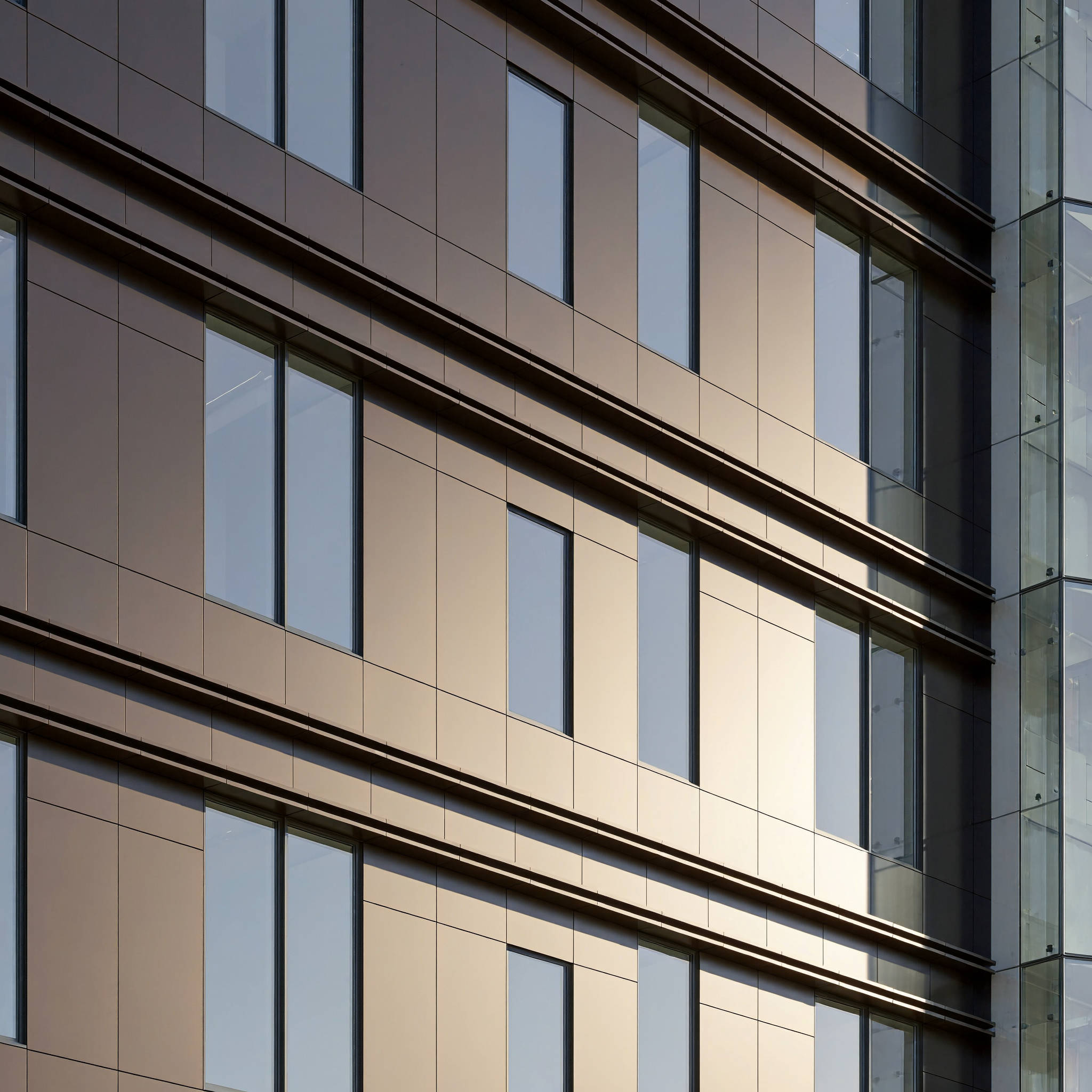
Architects and facade engineers who specify solid aluminium sheet cladding on mid-rise and high-rise projects frequently run into the same question during the shop-drawing phase: how do you handle thermal movement without compromising the tight joint lines that give the building its crisp, modern look? The answer sits at the intersection of alloy selection, panel sizing discipline, and fixing system design. Unlike composite materials that rely on a polyethylene core to absorb stress, solid aluminium sheets — typically 2.0 mm, 2.5 mm, or 3.0 mm thick and fabricated from alloys 5052, 5754, or 5083 — transfer every degree of temperature fluctuation directly into the panel body. A 4-metre panel under a 60°C temperature swing can elongate by nearly 5.7 mm. If the fixing system does not accommodate that movement, the result is oil-canning, fastener fatigue, or, in extreme cases, buckling that pulls panels out of plane. Getting this right is not about exotic engineering; it is about respecting the material's coefficient of linear thermal expansion — roughly 23.8 × 10⁻⁶ /°C for 5000-series alloys — and designing every connection point accordingly.
What Actually Happens When Solid Aluminium Sheets Heat Up
The physics is straightforward. Solid aluminium sheet cladding expands and contracts at roughly 2.38 mm per metre for every 100°C change. In real facade conditions, the surface temperature of a dark-coloured PVDF-coated panel on a summer afternoon in Dubai, Perth, or Phoenix can hit 80°C. That same panel might drop to -10°C overnight in a desert climate or during a cold snap in northern Europe. The 90°C delta translates to approximately 2.14 mm of movement per metre of panel length. Multiply that across a 6-metre continuous run and you are looking at 12.8 mm of cumulative movement that must go somewhere.
What complicates matters is that the aluminium substrate and the supporting subframe — often galvanised steel or aluminium extruded profiles — expand at different rates. Steel expands at roughly 12 × 10⁻⁶ /°C, about half the rate of aluminium. If the two materials are rigidly locked together, differential expansion introduces shear forces at every fixing point. Over hundreds of thermal cycles, those forces loosen rivets, elongate bolt holes, and degrade the PVDF or powder coating at stress concentration points, opening pathways for crevice corrosion.
Alloy Choice: 5052 vs 5754 vs 5083 and Why It Matters for Thermal Performance
Not all solid aluminium cladding sheets respond to thermal loading the same way. The 5000-series alloys — primarily 5052 (Al-Mg-Cr), 5754 (Al-Mg), and 5083 (Al-Mg-Mn) — dominate the architectural cladding market, but their subtle differences in magnesium content and temper designation affect both thermal expansion behaviour and the panel's resistance to stress corrosion cracking under cyclic thermal loading.
| Property | 5052-H32 | 5754-H22 | 5083-H116 |
|---|---|---|---|
| Thermal Expansion (×10⁻⁶/°C) | 23.8 | 23.9 | 24.2 |
| Tensile Strength (MPa) | 210–260 | 220–270 | 305–350 |
| Yield Strength (MPa) | 160–200 | 170–210 | 215–270 |
| Elongation (%) | 7–12 | 10–15 | 10–16 |
| Stress Corrosion Cracking Resistance | Good | Very Good | Excellent |
| Typical Cladding Thickness (mm) | 2.0 / 2.5 / 3.0 | 2.0 / 2.5 / 3.0 | 2.5 / 3.0 |
| Marine Environment Suitability | Moderate | Good | Excellent |
The expansion coefficients are close enough that no alloy eliminates the need for movement joints. But the yield strength differences matter when panels are restrained. A 5083-H116 panel can tolerate higher compressive stress before buckling than a 5052-H32 panel of the same thickness. For projects within 5 km of a coastline, 5083 or 5754 should be specified regardless, because the higher magnesium content (>3%) provides markedly better resistance to intergranular corrosion — a failure mode that thermal cycling can accelerate by repeatedly opening and closing micro-cracks in the oxide layer.
Panel Size Limits: Where the Numbers Break
Every fabricator has a preferred maximum panel size, but the thermal argument sets hard physical limits that no amount of stiffening can override. A common rule of thumb in the industry caps solid aluminium sheet cladding panels at 1,200 mm × 3,000 mm for 2.0 mm material and 1,500 mm × 4,000 mm for 3.0 mm material when using a cassette or tray system with perimeter returns. Beyond those dimensions, the panel's own thermal expansion can cause the flat face to bow — even with properly slotted fixings — because the return legs provide uneven restraint across the panel depth.
The bowing problem is particularly acute on dark-coloured panels (RAL 7016, 9005, 8019) installed on south-facing elevations in hot climates. A 3.0 mm thick, 1,500 mm wide panel with a 25 mm return leg, fixed at four corners with slotted holes at the top and fixed holes at the bottom, can still develop centre deflection of 3–5 mm under a 50°C temperature rise if the panel aspect ratio exceeds 3:1. Engineers at Futeng® have documented this behaviour across multiple projects and recommend keeping the aspect ratio below 2.5:1 for unperforated panels and below 2:1 for perforated panels where the open area exceeds 20%, since perforation reduces the panel's in-plane stiffness disproportionately.
Fixing System Design: Slotted Holes, Secret Fix, and Cassette Approaches
Slotted Hole Fixing with Exposed Fasteners
The most cost-effective method for managing thermal movement uses slotted holes at the top fixing points and round holes at the bottom. The bottom fixings act as the fixed datum; the top fixings allow vertical movement. Slot length is calculated as:
Slot Length = Panel Height (mm) × ΔT (°C) × 23.8 × 10⁻⁶ + 2 mm safety margin
For a 3,000 mm panel with a 70°C design temperature swing, that gives: 3,000 × 70 × 23.8 × 10⁻⁶ + 2 = 7.0 mm minimum slot length. In practice, most fabricators default to 8–10 mm slots to cover installation tolerances. The fastener should sit at the centre of the slot at the mean installation temperature (typically 15–20°C) so the panel has equal room to move in both directions.
A critical detail that is often missed: the fastener must not be fully torqued against the panel face. A nylon or EPDM washer under the screw head, tightened to just 60–70% of the fastener's rated torque, allows the panel to slide without abrading the coating. Overtightening creates a friction lock that defeats the slot entirely.
Secret Fix Cassette Systems
For architects who want a completely clean facade with no visible fasteners, secret-fix cassette systems dominate the specification landscape. The cassette — essentially a folded aluminium tray with return legs on all four sides — hangs on a horizontal rail system using extruded aluminium clips. Thermal movement is accommodated by allowing the cassette to slide along the rail. The bottom edge of each cassette typically sits in a drainage channel that also serves as the movement joint.
The catch with secret-fix systems is that they demand tighter fabrication tolerances. A 1 mm deviation in the fold line across a 3-metre cassette translates to a visible 2–3 mm step at the horizontal joint because the error compounds across adjacent panels. This is where factory-applied PVDF coil coating on solid aluminium sheets — rather than post-fabrication spray coating — pays dividends, because the consistent 25–35 μm dry film thickness across the entire sheet eliminates the coating thickness variation that can throw off fold-line accuracy.
Riveted Tray Systems with Subframe
Many contractors in Southeast Asia and the Middle East prefer riveted tray systems where the solid aluminium sheet is folded into a tray, stiffeners are riveted to the rear face, and the assembly is bolted to a steel subframe. Thermal movement in these systems must be managed at two levels: the panel-to-subframe connection and the subframe-to-structure connection. A common failure mode occurs when the aluminium tray is riveted rigidly to a steel subframe at multiple points, and the subframe itself is welded continuously to the building structure. The entire assembly becomes a bimetallic strip that bows outward as temperatures rise.
The fix is to introduce a thermal break — typically a 2 mm EPDM gasket or a nylon isolation pad — between the aluminium tray and the steel subframe at every fixing point, combined with slotted connections at the subframe-to-structure interface. This decouples the two materials and lets each expand independently.
Coating Systems Under Thermal Stress
Thermal cycling does not just affect the aluminium substrate; it also stresses the coating system. PVDF (polyvinylidene fluoride) coatings — typically 70% PVDF resin with 30% acrylic, applied at 25–35 μm dry film thickness — are the industry standard for solid aluminium sheet cladding on exterior facades. The PVDF resin's long-chain fluoropolymer structure gives it a coefficient of thermal expansion closer to that of aluminium than polyester or polyurethane coatings, which reduces the likelihood of micro-cracking at the coating-substrate interface during thermal cycling.
However, PVDF is not immune to thermal degradation. Testing per AAMA 2605 (the most demanding PVDF specification) requires 10 years of South Florida exposure with colour change below 5 Delta E units and chalking below 8 rating. For projects in the Middle East or other extreme-heat regions, specifying AAMA 2605 is non-negotiable. The cheaper AAMA 2604 (5-year performance) and AAMA 2603 (1-year) specifications use lower PVDF resin content and thinner films that will chalk and fade noticeably within 3–5 years under sustained high UV and thermal cycling.
Powder coating — typically polyester-based and applied at 60–80 μm — offers a lower-cost alternative but has a higher thermal expansion coefficient than PVDF. On dark colours in hot climates, powder-coated solid aluminium sheets can develop visible micro-crazing after 2–3 years of thermal cycling. The exception is FEVE (fluoroethylene vinyl ether) powder coatings, which approach PVDF performance but remain significantly more expensive and are only available from a limited number of applicators globally.
Movement Joints: Where, How Wide, and How to Detail Them
Movement joints in solid aluminium sheet cladding systems serve two purposes: they accommodate the cumulative expansion of the aluminium panels and they handle differential movement between the cladding and the building structure. The joint width is calculated as the sum of the expected thermal movement plus a tolerance for installation and structural deflection.
For a typical 15-metre uninterrupted run of cladding with a 70°C design temperature swing:
- Total thermal movement = 15,000 mm × 70°C × 23.8 × 10⁻⁶ = 25.0 mm
- Installation tolerance = ±3 mm
- Structural deflection allowance = ±5 mm (per local building code)
- Minimum joint width = 25 + 3 + 5 = 33 mm
In practice, joints narrower than 20 mm are difficult to seal reliably with backer rod and wet sealant. Joints wider than 40 mm become visually dominant and may require a cover trim or an expressed shadow gap detail. The sweet spot for most projects is 25–35 mm, which accommodates thermal movement across 10–15 metre panel runs while maintaining a clean visual line.
Joint placement should align with building movement joints, floor lines, and changes in building geometry. A common specification error is to run solid aluminium cladding continuously across a building expansion joint without introducing a matching movement joint in the cladding. The result is predictable: panels buckle or fasteners shear within the first year of seasonal cycling.
Wind Load and Thermal Load: The Combined Effect
Facade engineers often analyse wind load and thermal load separately, but the two interact in ways that can amplify panel deflection. Under positive wind pressure, a solid aluminium sheet deflects inward, which increases the panel's effective curvature and changes how thermal expansion manifests. A panel that is flat at 20°C and deflects inward under wind load at 70°C experiences a compound stress state: compressive thermal stress from constrained expansion combined with bending stress from wind pressure.
The ISO 7892 standard for curtain walling requires that cladding panels be tested under combined loading where applicable. For solid aluminium sheet cladding on high-rise projects where design wind pressures exceed 2.0 kPa, the combined stress should be checked against the alloy's yield strength with a safety factor of at least 1.5. A 3.0 mm 5052-H32 panel spanning 600 mm between stiffeners at 2.5 kPa wind pressure and 70°C thermal loading typically uses about 65–75% of its yield capacity — acceptable but worth verifying on a project-specific basis.
Fabrication Tolerances That Affect Thermal Performance
Thermal movement calculations assume that panels are fabricated to consistent dimensions, but real-world fabrication tolerances can eat into the movement allowance. Industry standards per ASTM B209 (Standard Specification for Aluminum and Aluminum-Alloy Sheet and Plate) allow thickness tolerances of ±0.08 mm for 2.0 mm sheet and ±0.10 mm for 3.0 mm sheet. More critically, the flatness tolerance for as-rolled sheet can be up to 3 mm per metre of width.
For cladding applications, fabricators should specify "stretcher-leveled" or "tension-leveled" sheet with a flatness tolerance of no more than 1.5 mm per metre. This tighter tolerance reduces the residual stress in the sheet that can cause oil-canning when thermal expansion adds compressive stress. It also ensures that panels sit flush against their fixing rails, so the slotted connections can slide freely rather than binding under friction from an out-of-flat panel.
Installation Sequencing and On-Site Adjustments
Even a perfectly engineered thermal movement system fails if panels are installed at extreme ambient temperatures. If a crew installs solid aluminium sheet cladding at 5°C on a winter morning, all the panels will be in their contracted state. When summer temperatures push the surface to 75°C, the cumulative expansion across a row of panels can close the movement joints completely, forcing panels into compression against each other.
The correct approach is to record the ambient temperature at the time of installation and adjust the joint width accordingly. If the design assumes a mean installation temperature of 20°C and the actual temperature is 5°C, the joint should be set 15°C × panel width × 23.8 × 10⁻⁶ wider than the nominal dimension. For a 1,200 mm wide panel, that is an additional 0.43 mm — small enough that it can be absorbed by the sealant joint, but for 3,000 mm panels, the 1.07 mm adjustment matters.
A practical field method: use a temperature gun to measure the panel surface temperature, consult a pre-calculated table of joint-width adjustments versus temperature, and shim each joint accordingly before tightening fixings. This takes an extra 30 seconds per panel and prevents callbacks that can cost tens of thousands in scaffolding and replacement panels.
Specifying Solid Aluminium Sheet Cladding for Thermal Performance: A Practical Checklist
- Select 5052-H32 for general applications, 5754-H22 for coastal projects, or 5083-H116 for marine environments and high-stress facades.
- Limit panel dimensions to 1,200 × 3,000 mm (2.0 mm) or 1,500 × 4,000 mm (3.0 mm) with aspect ratios below 2.5:1.
- Design slotted fixings with slot length = panel height × ΔT × 23.8 × 10⁻⁶ + 2 mm, and torque fasteners to 60–70% of rated capacity with a nylon washer.
- Specify PVDF coating to AAMA 2605 for any project where facade longevity beyond 10 years is required.
- Place movement joints every 10–15 metres of uninterrupted cladding run, with minimum 25 mm joint width.
- Verify combined wind-plus-thermal stress against yield strength with a safety factor of 1.5 or greater.
- Specify stretcher-leveled sheet with flatness tolerance ≤1.5 mm per metre.
- Record installation temperature and adjust joint widths on site.
Solid aluminium sheet cladding remains one of the most durable and architecturally flexible facade materials available to the construction industry. Its long-term performance depends less on the material itself — aluminium is inherently corrosion-resistant and dimensionally predictable — and more on the engineering discipline applied to its fixing and jointing. A facade that gracefully handles 50 years of thermal cycling is not built from a different alloy; it is built from the same 5052-H32 sheet as every other project, but with slotted holes cut to the right length, fasteners torqued to the right spec, and joints placed where the physics says they belong. Getting those details right in the specification and shop-drawing phase costs nothing extra in material and saves the project from the expensive, visible, and reputation-damaging consequences of a facade that cannot handle its own thermal reality.