Aluminium Solid Sheet Wind Load Engineering for High Rise and Coastal Facades
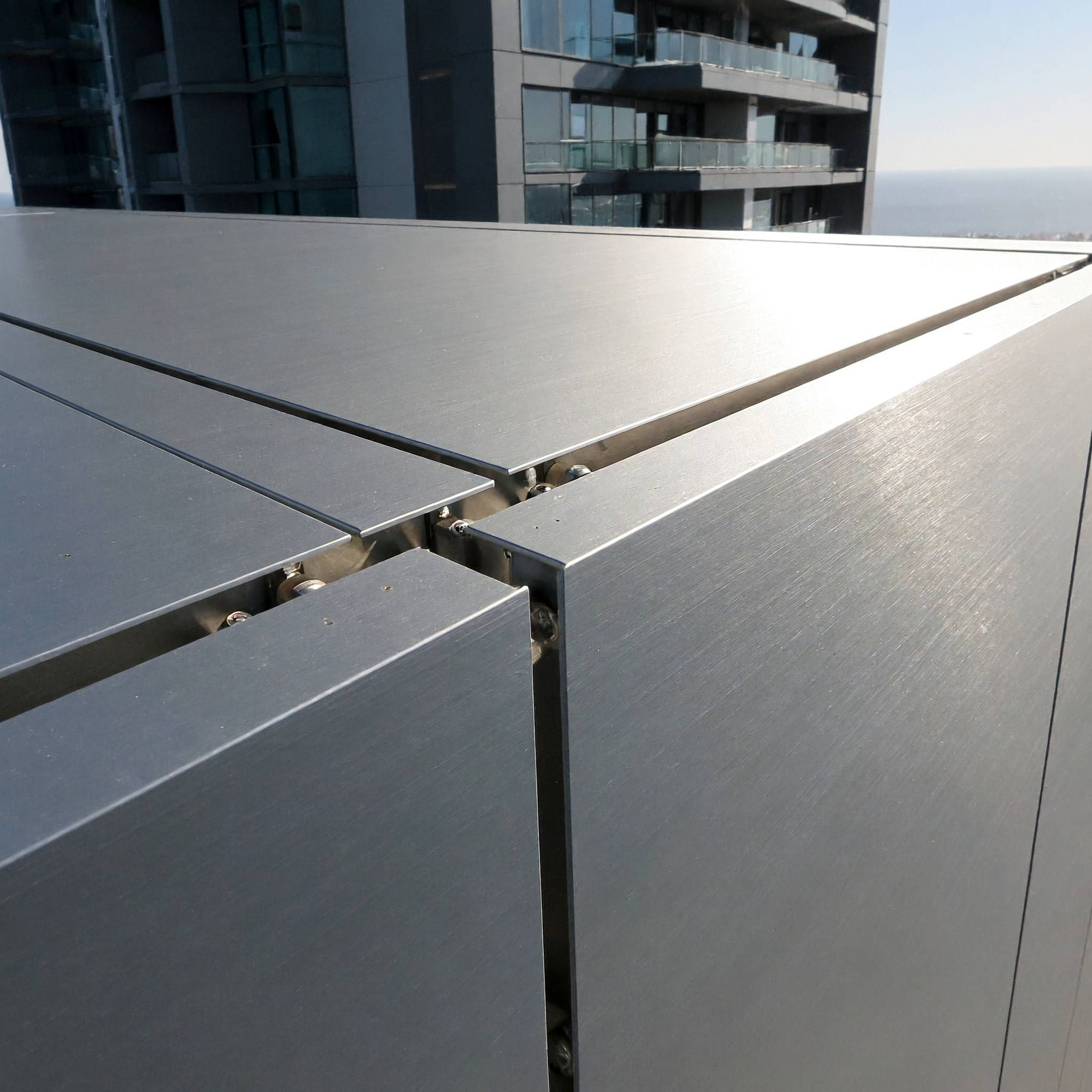
Specifying the right cladding material for a high-rise facade or a coastal commercial building means confronting a long list of performance variables. Wind load resistance, fire compliance, thermal movement, and long-term coating integrity all sit on the table. Among the options, the aluminium solid sheet has gained steady traction with facade engineers who need a single-skin metal panel that does not rely on a polyethylene or mineral core for its structural performance. A solid aluminium sheet — typically available in 2.0 mm, 2.5 mm, and 3.0 mm thicknesses — brings its own stiffness to the job, derived entirely from the base alloy and the work-hardening imparted during the rolling process. This article focuses on one specific, often under-discussed challenge: how an aluminium solid sheet performs under high wind load conditions, and what the supporting engineering calculations actually look like when you move from a sheltered suburban site to a fully exposed coastal tower.
Why Wind Load Dictates Solid Sheet Specification
Wind load is not a single number. It varies with building height, terrain category, local topography, and the building's shape. For cladding specifiers, the critical output is the design wind pressure — expressed in Pascals (Pa) or kilopascals (kPa) — that each panel must resist without exceeding its allowable deflection. Most international codes, including AS/NZS 1170.2, EN 1991-1-4, and ASCE 7, require facade panels to limit deflection to L/60 or L/90 of the span under serviceability wind loads, where L is the distance between fixing centres. An aluminium solid sheet, unlike a composite panel, derives its bending resistance purely from its section modulus. That makes thickness selection the single most consequential decision when wind pressures climb above 2.0 kPa.
A 2.0 mm thick aluminium solid sheet spanning 600 mm between stiffeners might handle a 1.5 kPa design pressure comfortably. Push that same panel to a 3.5 kPa zone — common on upper floors of a 40-storey structure near open water — and the deflection can exceed code limits unless you either reduce the span or step up to 2.5 mm or 3.0 mm material. Facade consultants working on projects from Dubai Marina to the Auckland waterfront routinely run finite element analysis on solid aluminium panels to verify that the combination of alloy temper, sheet thickness, and fixing layout stays within both strength and serviceability limits. The alloy choice matters here: EN AW-5005 (AlMg1) in H14 or H24 temper is a common specification for architectural solid sheets, offering a useful balance of formability and yield strength around 120–140 MPa.
Understanding the Mechanics: How a Solid Aluminium Sheet Resists Bending
The engineering model for a flat rectangular aluminium solid sheet under uniform wind pressure is essentially a plate bending problem. For panels supported on four sides with mechanical fixings, the maximum bending stress and deflection depend on the panel aspect ratio, the boundary conditions at the fixings, and the flexural rigidity of the sheet. The flexural rigidity D is given by:
D = E × t³ / [12 × (1 - ν²)]
Where E is the elastic modulus of aluminium (approximately 70,000 MPa for 5005 alloy), t is the sheet thickness in mm, and ν is Poisson's ratio (around 0.33 for aluminium). Notice the t³ term — it means that increasing sheet thickness from 2.0 mm to 3.0 mm raises the flexural rigidity by a factor of roughly 3.4, not just 1.5. This cubic relationship explains why a seemingly modest thickness upgrade can dramatically reduce deflection under high wind loads. A 3.0 mm aluminium solid sheet spanning 800 mm between fixings can often outperform a 2.0 mm sheet on a 500 mm span, giving the design team more flexibility with substructure spacing and potentially reducing the total linear metres of aluminium framing required.
For a uniformly loaded rectangular plate with simply supported edges, the maximum deflection at the centre can be estimated using coefficients from plate theory. A practical approximation used by many facade engineers is:
δ_max = α × q × b⁴ / D
Where q is the uniform wind pressure, b is the shorter span dimension, and α is a coefficient that depends on the aspect ratio a/b. For a square panel (a/b = 1.0), α is approximately 0.00406. For a panel with a/b = 1.5, α drops to around 0.00772. These numbers are available in standard references such as Roark's Formulas for Stress and Strain. Running these calculations early in the design phase helps avoid the costly discovery, late in construction, that specified panels will require additional intermediate stiffeners to meet deflection criteria.
Alloy Selection and Its Impact on Wind Load Performance
Not all aluminium solid sheets are metallurgically identical. The three alloys most commonly encountered in architectural cladding are EN AW-5005, EN AW-5052, and EN AW-5754. Each brings a different yield strength to the wind load calculation, and the choice can mean the difference between passing and failing a serviceability check at 3.0 kPa.
| Alloy Designation | Temper | Yield Strength (MPa, min) | Tensile Strength (MPa) | Typical Cladding Application |
|---|---|---|---|---|
| EN AW-5005 (AlMg1) | H14 / H24 | 120 | 145–185 | Standard architectural facades, inland |
| EN AW-5052 (AlMg2.5) | H32 | 160 | 210–260 | Coastal facades, high-wind zones |
| EN AW-5754 (AlMg3) | H22 / H24 | 130–190 | 220–270 | Marine environments, industrial buildings |
The 5052 alloy in H32 temper offers roughly 33% higher yield strength than 5005-H14. In a wind-dominated design, that can translate directly into the ability to use a thinner sheet or wider fixing centres while maintaining the same deflection performance. The trade-off is cost and availability: 5052 sheet typically carries a 10–15% price premium over 5005, and lead times from some mills can be longer. For a project in a cyclone-prone region — say, a resort building in Mauritius or a hospital in northern Queensland — the premium is usually justifiable. Suppliers such as Futeng® maintain stock of both 5005 and 5052 aluminium solid sheets in standard cladding thicknesses, which can shorten procurement timelines when the wind load analysis pushes the specification toward the higher-strength alloy.
Fixing Systems and Their Influence on Panel Capacity
The wind load capacity of an aluminium solid sheet is not solely a function of the sheet itself. The fixing method — whether it is a perimeter cassette system with return legs, a face-fixed rivet arrangement, or a secret-fix hanging system — determines the effective boundary conditions that feed into the plate bending equations. A panel held in a fully interlocked cassette with folded return legs on all four edges behaves closer to a clamped plate than a simply supported one, which can reduce the maximum bending moment by up to 40% for the same pressure and span.
Face-fixed panels using stainless steel rivets or screws at discrete points present a different challenge. The localised stress concentration around each fastener hole needs to be checked against the bearing strength of the aluminium solid sheet. For a 2.5 mm thick 5005-H14 sheet, the bearing capacity at a 5 mm diameter fastener hole is typically in the range of 1.5–2.0 kN per fixing, assuming standard edge distances. Under a 3.0 kPa wind load, a 1200 mm × 600 mm panel experiences a total force of 2.16 kN, distributed across perhaps six or eight fixings. The per-fixing load is well within bearing limits, but the panel designer must also verify that the fixing layout does not create unsupported edge lengths that flutter under cyclic wind loading.
Cyclic wind loading — the repeated pressure and suction cycles that a facade experiences over its service life — introduces fatigue considerations that are absent from a simple static strength check. Aluminium alloys do not exhibit a true fatigue limit, meaning that even low-stress cycles accumulate damage over millions of cycles. The relevant standard for wind-induced fatigue on building facades is not as mature as the static wind codes, but the AAMA 501.1 and 501.4 test protocols provide a framework for dynamic water penetration and structural performance testing that includes cyclic pressure loading. Specifying an aluminium solid sheet for a high-rise in a typhoon zone should trigger a discussion about cyclic testing requirements, not just a static pressure rating.
Deflection Limits: The Real-World Constraint
Strength failure — the panel actually tearing or buckling — is rare in properly specified aluminium solid sheet cladding. What drives thickness selection in practice is the serviceability deflection limit. A panel that deflects 25 mm under peak wind load might be structurally safe, but it will visibly distort the facade, potentially open sealant joints, and create the perception of a failing building envelope. Most facade specifications set the allowable deflection at L/90 for panels spanning between supports, with some clients pushing for L/120 on prestige commercial towers where visual flatness is non-negotiable.
Consider a 2.0 mm aluminium solid sheet on a 700 mm × 700 mm grid. Under a 2.5 kPa design wind pressure, the centre deflection calculated from plate theory is approximately 8–10 mm. That equates to roughly L/70 — failing an L/90 criterion. The same panel in 2.5 mm thickness deflects around 4–5 mm, comfortably meeting L/90. The cost difference between 2.0 mm and 2.5 mm solid sheet is typically in the range of 15–20% on the raw material, but when weighed against the cost of adding intermediate stiffeners or reducing the grid spacing (which adds framing cost), the thicker sheet often emerges as the more economical solution overall. This trade-off is well documented in guidance from the European Aluminium Federation, which publishes technical bulletins on the structural design of aluminium building products.
Coating Systems and Wind-Driven Rain Performance
Wind load analysis for an aluminium solid sheet is not complete without considering what happens when wind and rain combine. Wind-driven rain can penetrate behind the panel plane if joint design and sealant detailing are not coordinated with the expected panel deflection. A panel that deflects 6 mm under peak wind load will open and close the perimeter joints cyclically, and the sealant must accommodate this movement without losing adhesion.
The coating system on the aluminium solid sheet also plays a role in long-term wind resistance, indirectly. A PVDF (polyvinylidene fluoride) coating applied to a nominal dry film thickness of 25–35 microns — in compliance with ASTM D5720 for architectural coatings — provides the UV and chemical resistance needed to prevent surface degradation that could, over decades, reduce the effective thickness of the aluminium substrate through pitting corrosion. In coastal environments with salt-laden winds, a three-coat PVDF system over a chrome-based pretreatment is the standard specification. Some manufacturers offer a four-coat system with a clear topcoat for additional gloss retention, though the incremental wind load benefit is nil — this is purely an aesthetic and durability consideration.
For projects within 5 km of breaking surf, the aluminium solid sheet alloy should be 5052 or 5754 rather than 5005, regardless of the coating specification. The magnesium content in 5005 (around 1.0%) provides only moderate corrosion resistance compared to 5052 (2.5% Mg) and 5754 (3.0% Mg). The ISO 12944 series on corrosion protection of steel structures provides a useful environmental classification framework that is often applied by analogy to aluminium cladding specifications, even though the standard itself focuses on steel.
Thermal Movement: The Hidden Variable in Wind Load Design
An aluminium solid sheet expands and contracts with temperature changes at a rate of approximately 24 × 10⁻⁶ per °C. On a 3-metre-long panel subjected to a 60°C temperature swing (from a cold winter night to direct summer sun on a dark-coloured panel), the thermal elongation is roughly 4.3 mm. If the fixing system does not allow this movement, the panel can buckle — and a buckled panel presents a different, less predictable geometry to the wind than the flat plate assumed in the design calculations.
The interaction between thermal movement and wind load is particularly important for secret-fix systems where the panel edges are constrained in sliding clips. If the clips are overtightened during installation, thermal expansion can induce compressive stresses in the panel that, when combined with wind suction on the leeward face of the building, can trigger local buckling at stress levels below the nominal yield strength. The solution is a fixing system with controlled slip — typically a stainless steel clip that allows 2–3 mm of movement per fixing point — specified alongside an aluminium solid sheet of sufficient thickness to resist buckling under the combined thermal and wind load. The Standards Australia technical committee BD-086 has published guidance on accommodating thermal movement in metal wall cladding that is referenced by many Asia-Pacific facade consultants.
Practical Specification Workflow for Wind-Loaded Facades
Bringing all these factors together, a robust specification workflow for an aluminium solid sheet on a wind-exposed facade looks like this:
- Establish the design wind pressures. Engage the project wind engineer or use the relevant national code (ASCE 7, EN 1991-1-4, AS/NZS 1170.2) to determine peak positive and negative pressures for each facade zone. Corner zones typically see 1.5× to 2.0× the pressure of the field area.
- Select candidate sheet thicknesses. Based on the architectural intent and the available substructure grid, identify feasible combinations of aluminium solid sheet thickness (2.0, 2.5, 3.0 mm) and fixing spacing.
- Run deflection checks. Use plate theory or FEA software to verify that each candidate combination meets the project's deflection limit (typically L/90) under the serviceability wind load.
- Check strength. Verify that the maximum bending stress does not exceed the allowable stress for the chosen alloy and temper, including any reduction factors for welding or forming if the panel has folded edges.
- Check fixings. Calculate per-fastener loads and verify bearing capacity, pull-out, and pull-over for the selected fastener type and sheet thickness.
- Address thermal movement. Confirm that the fixing system can accommodate the calculated thermal expansion range without inducing buckling.
- Specify coating and alloy for environment. Match the alloy grade (5005, 5052, 5754) and coating system (PVDF two-coat, three-coat, or four-coat) to the site's corrosion category.
- Require testing. For high-wind or high-exposure projects, include a requirement for AAMA 501.1 dynamic testing or a project-specific mock-up test that cycles the panel through the design pressure range.
This workflow is not theoretical. Facade contractors on projects across Southeast Asia and the Middle East have applied it repeatedly, and the availability of mill-finish and pre-coated aluminium solid sheet from established suppliers means that lead times can be managed if the specification is locked in early. The key is to avoid the trap of treating wind load as a simple pressure rating on a product data sheet. It is a system-level problem that involves the sheet, the fixings, the substructure, and the building's aerodynamics.
When a Thicker Sheet Saves Money
There is a persistent assumption that specifying a thinner aluminium solid sheet always reduces cost. On a raw material basis, that is true. But on an installed-system basis, the economics can invert. A 2.0 mm sheet on a high-wind facade may require a substructure grid of 500 mm × 500 mm to meet deflection limits, while a 3.0 mm sheet on an 800 mm grid might use 40% fewer lineal metres of aluminium framing and 40% fewer fixings. The framing and labour savings can exceed the incremental material cost of the thicker sheet. This is not a universal rule — it depends on local labour rates, framing costs, and the specific wind pressures — but it is a calculation worth running before finalising the specification.
"We have seen multiple projects where switching from 2.0 mm to 2.5 mm aluminium solid sheet reduced the total facade system cost by 8–12% once framing and installation labour were factored in. The thicker panel allowed wider stiffener spacing without compromising the L/90 deflection target." — Facade engineering team, Southeast Asia
Wind load engineering for solid aluminium cladding is ultimately about matching the panel's flexural rigidity to the pressure environment. The aluminium solid sheet, with its monolithic cross-section and predictable mechanical properties, lends itself well to this kind of analysis. There is no core material with different creep behaviour, no delamination failure mode to check, and no shear transfer mechanism to verify. The engineering is direct: thickness, alloy, span, fixings. Get those four variables right, and the panel will perform.
The projects that get into trouble are the ones where wind load is treated as an afterthought — where the architect selects a panel thickness based on visual flatness alone, and the contractor orders the material before the facade engineer has run the zone-by-zone pressure numbers. In a typhoon-prone region or on a 50-storey tower where the upper-floor wind pressures can exceed 4.0 kPa, that sequence of decisions can lead to panels that deflect visibly, leak at the joints, or require expensive remedial stiffening after installation. Starting with the wind load, working through the plate mechanics, and specifying the aluminium solid sheet thickness that the numbers demand is the only approach that consistently delivers a facade that stays flat, dry, and secure across its design life.