Acoustic Aluminium Panels Engineering Perforation Geometry and Structural Design for Facade Noise Control
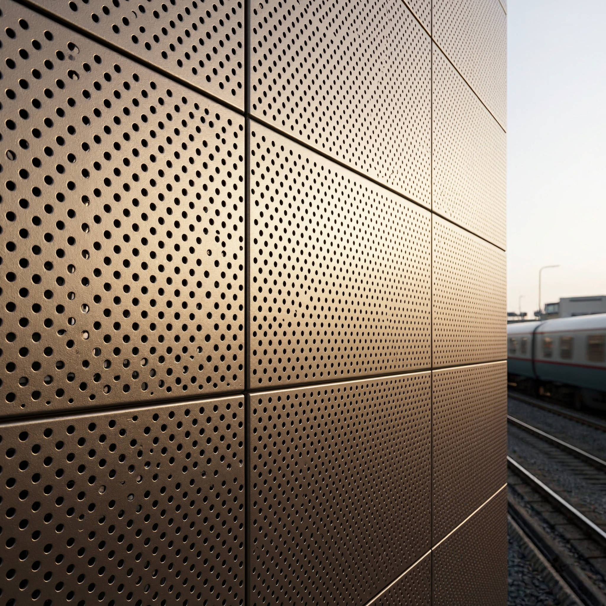
When a commercial building project demands both acoustic performance and exterior durability, specifiers increasingly turn to acoustic aluminium panels. These are not lightweight composite sheets but solid aluminium panels — typically 2.0mm, 2.5mm, or 3.0mm thick — engineered with perforation patterns and backed by acoustic absorption media. The core value proposition is straightforward: a single facade element that attenuates noise while meeting the structural, fire, and weathering requirements of a modern curtain wall. For general contractors and facade engineers, understanding how perforation geometry, rear loading, and panel thickness interact determines whether the installed system actually hits the specified sound reduction targets — or falls short during commissioning tests.
How Solid Aluminium Acoustic Panels Actually Work
The mechanism behind acoustic aluminium panels relies on a Helmholtz resonator principle. Sound waves strike the perforated aluminium face, pass through the apertures, and encounter a porous absorption layer — typically mineral wool, rock wool, or acoustic fleece — bonded behind the metal skin. The air trapped between the solid aluminium sheet and the absorber acts as a spring. Tuning the perforation diameter, pitch, and open-area percentage shifts the resonant frequency to target specific noise bands.
What separates solid aluminium acoustic panels from lighter alternatives is mass. A 2.5mm solid aluminium sheet weighs approximately 6.8 kg/m² before perforation. That mass provides inherent low-frequency transmission loss that thinner composite panels cannot match. When combined with a 50mm mineral wool backing (density 60-80 kg/m³), the composite system can achieve weighted sound absorption coefficients (αw) between 0.75 and 0.95, depending on the perforation specification.
The acoustic performance follows ISO 354:2003 for laboratory measurement of sound absorption, while the overall panel system must comply with EN 14783 for fully supported metal sheet roofing products or equivalent ASTM standards in North American markets. Specifiers should request third-party test reports that document absorption coefficients across the full 100 Hz to 5000 Hz frequency range — not just a single NRC figure.
Perforation Geometry and Acoustic Outcomes
The perforation pattern on an aluminium acoustic panel is not decorative. It is the primary engineering variable that controls acoustic behaviour. Three parameters interact: hole diameter, centre-to-centre pitch, and the resulting open-area ratio. Getting this right requires balancing acoustic targets against structural integrity and cleanability.
Common industrial configurations include:
- 1.5mm diameter, 3.0mm pitch: approximately 23% open area. Effective for mid-to-high frequency absorption (500 Hz – 4000 Hz). Suitable for rail corridor noise and urban traffic attenuation.
- 2.0mm diameter, 5.0mm pitch: approximately 14.5% open area. Broader absorption curve with some low-frequency extension. Often specified for mixed-use developments near entertainment venues.
- 3.0mm diameter, 8.0mm pitch: approximately 11% open area. Prioritises structural stiffness and weather resistance while providing moderate acoustic dampening. Common in airport terminal facades.
- Micro-perforation (0.5mm – 0.8mm diameter): open areas below 5%. Relies on viscous boundary layer effects for absorption. Requires precise CNC punching and is sensitive to paint bridging during PVDF coating.
A critical detail often overlooked: when PVDF fluorocarbon coating is applied post-perforation, the liquid paint can partially fill small holes, reducing effective open area by 1-3 percentage points. This must be accounted for in the acoustic model. Factories with controlled spray parameters — such as those used by Futeng® for their solid aluminium acoustic panel production — maintain strict tolerance on post-coating hole diameter to preserve the specified acoustic impedance.
Structural Considerations for Perforated Solid Aluminium Facades
Punching holes through a 2.5mm or 3.0mm aluminium sheet reduces its section modulus. A panel with 23% open area loses roughly 30-40% of its bending stiffness compared to an unperforated sheet of the same thickness. This has direct consequences for wind load resistance and fixing design.
Engineers should approach the structural design in three steps:
- Effective thickness calculation: Apply a stiffness reduction factor based on open-area ratio. For preliminary estimates, a panel with 20% open area may behave structurally like an unperforated sheet of approximately 70% of its nominal thickness.
- Support spacing adjustment: Reducing the maximum span between fixing rails compensates for stiffness loss. A 2.5mm solid aluminium panel spanning 600mm between supports when unperforated may need spacing reduced to 450-500mm at 20% open area, depending on the design wind load.
- Stress concentration at perforations: The holes create stress risers. Fatigue testing per ASTM E466 may be warranted for panels in high-cycle wind environments such as coastal high-rises or bridges.
Material grade matters. EN AW-5754 (Al-Mg3) offers better corrosion resistance and fatigue performance than standard 3003 alloys, making it the preferred choice for perforated acoustic panels in marine or industrial atmospheres. The temper should be H22 or H42 — work-hardened enough for strength but retaining sufficient ductility for perforation without edge cracking.
Acoustic Backing Materials and Fire Performance
The sound absorption layer behind the perforated aluminium face is equally important as the metal itself. Common options include:
| Backing Material | Density (kg/m³) | Operating Temperature | Fire Classification (EN 13501-1) | Typical Application |
|---|---|---|---|---|
| Mineral wool (stone) | 60–100 | Up to 750°C | A1 (non-combustible) | High-rise facades, tunnel linings |
| Glass wool | 16–48 | Up to 350°C | A1 or A2 | Interior acoustic ceilings |
| Acoustic fleece (polyester) | 200–400 | Up to 120°C | B-s1,d0 | Lightweight soffit panels |
| Melamine foam | 8–12 | Up to 200°C | B-s1,d0 | Cleanroom and laboratory panels |
For exterior facade applications, mineral wool with a black glass-fibre facing is the industry standard. The facing prevents fibre migration through the perforations — a phenomenon that can degrade acoustic performance over time and create visible staining on the panel face. The mineral wool must also be hydrophobic to prevent moisture retention, which would add dead load and accelerate aluminium corrosion at the contact interface.
Fire strategy must consider the entire build-up. While solid aluminium itself is non-combustible (A1 rating per EN 13501-1 when uncoated), the PVDF coating and acoustic backing introduce combustibility. The complete system should be tested as an assembly. For projects above 18 metres in England and Wales, compliance with Approved Document B requires that all components in the external wall be of limited combustibility — a requirement that has driven increased adoption of A1-rated stone wool backings paired with solid aluminium acoustic panels.
Coating Systems and Long-Term Acoustic Stability
The coating on acoustic aluminium panels serves dual purposes: weather protection and maintenance of acoustic properties. A standard architectural PVDF (polyvinylidene fluoride) system consists of a chrome-based conversion coating, a primer layer (5–8 microns), and a colour topcoat (25–30 microns). Total dry film thickness typically falls between 35–45 microns.
For perforated acoustic panels, the coating process introduces specific risks. Spray application can bridge small holes; roller coating is generally unsuitable for perforated sheets. The preferred method is electrostatic spray with controlled viscosity to minimise bridging. Post-coating inspection should verify that no hole has its diameter reduced by more than 10% from the specified value.
Coating performance benchmarks relevant to acoustic panel longevity include:
- AAMA 2605: The highest performance specification for architectural coatings, requiring 10-year Florida exposure with colour retention (ΔE ≤ 5), chalk resistance (rating ≥ 8), and gloss retention above 50%.
- ISO 16474-2: Accelerated weathering using xenon-arc lamps, typically run to 3000–5000 hours for premium PVDF systems.
- Salt spray resistance (ISO 9227): Minimum 3000 hours for marine-grade applications, with no blistering or creep from the scribe exceeding 2mm.
A coating failure on an acoustic panel is more consequential than on a standard facade panel. Corrosion starting at the rim of a perforation can progressively enlarge the hole, changing its acoustic impedance. What was a precisely tuned resonator becomes an unpredictable noise element. For this reason, some manufacturers — Futeng® included — apply a double-pass coating process on perforated panels, ensuring full coverage of the internal hole walls.
Installation Methods and Their Impact on Acoustic Performance
How an acoustic aluminium panel is fixed to the substructure directly affects its sound absorption performance. Three common systems exist, each with distinct acoustic implications:
1. Cassette system with visible joints (20–25mm gap): The open joint allows sound to reach the absorber from the front and also permits diffraction around panel edges. This can slightly improve broadband absorption but reduces the overall sound transmission loss of the wall assembly. Requires careful detailing of the joint backing to prevent whistling in high-wind conditions.
2. Secret-fix hook-on system (8–12mm joint): Tighter joints provide better transmission loss but can create localised reflections at the joint lines. The narrow gap is still sufficient for thermal movement of the aluminium without imposing loads on adjacent panels.
3. Structural silicone bonded (zero visible joint): Used where a monolithic appearance is desired. The continuous surface eliminates joint diffraction but also seals the panel face. Acoustic absorption then relies entirely on the perforations, making accurate open-area specification critical. Silicone selection must account for the acoustic vibration environment — high-modulus silicones can crack under cyclic loading.
Behind all three systems, the cavity depth between the panel rear and the structural wall or insulation layer functions as part of the acoustic system. A 100–200mm cavity shifts the resonant absorption peak toward lower frequencies, which can be advantageous for traffic noise attenuation. The cavity should be continuous and uninterrupted by horizontal framing members that would subdivide the air volume and alter the resonant behaviour.
Estimating Acoustic Performance: Practical Data for Specifiers
While laboratory testing remains essential for final specification, preliminary estimates help narrow options during design development. The table below provides indicative sound absorption coefficients (α) for a 2.5mm solid aluminium panel with 2.0mm perforations at 5.0mm pitch (approximately 14.5% open area), backed with 50mm stone wool (80 kg/m³) and installed with a 150mm rear cavity:
| Frequency (Hz) | 125 | 250 | 500 | 1000 | 2000 | 4000 | NRC |
|---|---|---|---|---|---|---|---|
| Absorption Coefficient (α) | 0.25 | 0.55 | 0.80 | 0.90 | 0.85 | 0.70 | 0.75 |
These values shift with cavity depth. Reducing the cavity to 50mm moves the peak absorption upward by approximately one octave. Increasing to 300mm extends low-frequency performance but requires additional substructure depth — adding cost and potentially encroaching on usable floor area in retrofit scenarios.
For projects requiring sound transmission class (STC) or outdoor-indoor transmission class (OITC) ratings, the complete wall assembly must be modelled. A typical build-up of 2.5mm perforated aluminium panel + 50mm mineral wool + 150mm air cavity + 150mm concrete backup wall can achieve STC ratings above 55, making it suitable for buildings adjacent to highways, railways, or industrial zones. The relevant test standard is ASTM E90 for laboratory measurement of airborne sound transmission loss.
Weight, Handling, and Logistics
Solid aluminium acoustic panels are heavier than their composite counterparts, and this affects every stage from fabrication to installation. A 2.5mm perforated panel at 1.2m × 2.4m weighs approximately 19.5 kg excluding the backing material. Add 50mm of 80 kg/m³ stone wool, and the total panel weight approaches 30 kg.
For the procurement team, weight translates to freight cost. A 20-foot container can typically hold 800–1200 m² of solid aluminium acoustic panels, depending on panel dimensions and packaging density. Ocean freight from Asian manufacturing hubs to European or North American ports should be budgeted at approximately USD 3.50–6.00 per square metre, though rates fluctuate with fuel surcharges and seasonal demand.
On-site handling requires suction lifters rated for the panel weight, with cup placement adjusted to avoid the perforated zone — suction cups lose grip on perforated surfaces. Edge protection is mandatory during lifting to prevent bending at the thinnest cross-sections between holes. For panels with open areas above 20%, temporary stiffening frames may be needed during transport and installation, adding approximately 8–12% to the handling cost but reducing the risk of panel damage to near zero.
Quality Assurance and Factory Testing
Before shipping, acoustic aluminium panels should undergo factory acceptance testing that goes beyond visual inspection. The following checks are standard for projects where acoustic performance is contractually specified:
- Open-area verification: Using digital optical scanning on a statistical sample (typically 5% of panels or minimum 10 panels per batch), the actual open area is measured and compared to the specified value. Tolerance should be within ±1.5 percentage points.
- Coating adhesion: Cross-hatch testing per ISO 2409 on a witness sample perforated alongside the production panels. The coating around hole rims is the most vulnerable zone.
- Panel flatness: Perforation releases residual stresses in the aluminium sheet, which can cause warping. A 2.5mm panel should maintain flatness within 0.5% of its diagonal dimension after perforation.
- Impedance tube testing: For critical projects, a random sample can be tested in an impedance tube per ISO 10534-2 to verify the absorption coefficient at the design frequency. This provides a rapid quality check without requiring a full reverberation room test.
For projects referencing ISO 354:2003 or ASTM E90 for acoustic performance, the test reports should come from an ISO 17025-accredited laboratory. In-house test data has its place during product development but should not substitute for third-party certification in contract documentation.
Cost Drivers and Budgeting
The cost of solid aluminium acoustic panels is driven by five primary factors, and understanding each helps procurement managers make informed trade-offs:
Perforation complexity: A standard 2.0mm staggered perforation pattern costs less than micro-perforation or custom geometric patterns. The latter requires slower CNC punch speeds and more frequent tool changes. Budget a 20–40% premium for custom patterns over standard staggered layouts.
Open-area ratio: Higher open area means more punching time and higher scrap rates from the punched slugs. Above 25% open area, panel handling becomes more delicate and reject rates increase.
Alloy selection: EN AW-5754 costs approximately 10–15% more than EN AW-3003 but delivers measurably better corrosion fatigue resistance — a factor that matters when the panel is perforated and exposed to coastal air.
Backing material specification: A1-rated stone wool with black facing costs roughly twice as much as standard glass wool. For a 10,000 m² project, this single decision can swing the budget by USD 40,000–60,000.
Coating specification: Standard PVDF (AAMA 2604) versus premium PVDF (AAMA 2605) adds approximately USD 8–12 per square metre. The premium is justified for projects within 5 km of salt water or in regions with UV indices above 8.
For preliminary budgeting, solid aluminium acoustic panels with standard perforation, A1 stone wool backing, and AAMA 2605 coating typically fall in the range of USD 180–280 per square metre supplied to site, excluding the support substructure and installation labour.
Common Specification Errors and How to Avoid Them
After reviewing project specifications across two dozen international tenders, several recurring mistakes stand out. Each one can lead to panels that look correct on the shop drawing but fail to perform acoustically:
"Specifying an NRC value without stating the mounting condition is meaningless. An NRC of 0.85 measured in a Type A mounting (panel laid directly on the floor of the reverberation room) will not be replicated in an E-400 mounting (400mm air cavity). Always reference the mounting type per ASTM E795."
Other common pitfalls include: specifying the perforation percentage without the hole diameter (they are interdependent); requiring a PVDF colour that necessitates a primer incompatible with the acoustic fleece adhesive; and designing panel joints that align with structural columns — creating uninterrupted vertical channels that can transmit sound between floors.
A robust specification references the complete system: aluminium alloy and temper, perforation geometry with tolerances, coating system and standard, backing material type and density, mounting condition for acoustic testing, and the accredited laboratory that will provide the test reports. Suppliers like Futeng® who manufacture solid aluminium panels with integrated acoustic backing can provide system-level warranties that cover both the aluminium and the acoustic assembly — a detail worth confirming during the pre-qualification stage.
Maintenance and Service Life
One of the strongest arguments for acoustic aluminium panels on exterior facades is their service life. A properly coated solid aluminium panel in a non-marine environment can deliver 30–40 years of structural and acoustic performance with minimal maintenance. The maintenance regime is straightforward:
- Annual inspection: Check for visible corrosion at perforation rims, particularly on panels facing prevailing winds. Check that drainage paths behind the panels are clear — blocked drainage can trap moisture against the acoustic backing.
- Cleaning (every 2–5 years depending on exposure): Use pH-neutral detergent and low-pressure water (AAMA 610.1 provides cleaning guidelines for architectural aluminium). Avoid wire brushes or abrasive pads that would scratch the PVDF coating and create initiation points for filiform corrosion.
- Acoustic re-testing (every 10–15 years for critical installations): In transportation infrastructure projects, periodic sound absorption measurement verifies that the panels still meet the original specification. Degradation of the mineral wool binder over decades can shift absorption characteristics.
The recyclability of solid aluminium is an additional consideration at end-of-life. Unlike composite panels that require separation of the aluminium skins from the core material, solid aluminium acoustic panels with mechanically attached mineral wool backing can be fully disassembled. The aluminium is 100% recyclable without loss of properties, and the stone wool can be processed for use as a raw material in new mineral wool production — a closed-loop scenario that aligns with ISO 14021 requirements for self-declared environmental claims.
For the specifier and the contractor, acoustic aluminium panels represent an engineering system where material choice, perforation design, backing specification, and installation detail are interdependent. Success comes from treating them as a single integrated package rather than a metal panel with an acoustic afterthought. The projects that achieve both the required sound absorption and the required facade durability are those where the acoustic consultant, facade engineer, and panel manufacturer collaborate from schematic design onward — not where the perforation pattern is value-engineered after tender award.