Square Perforated Aluminum Sheet Engineering for Facade Wind Load and Corrosion Control
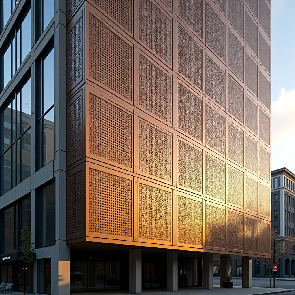
A square perforated aluminum sheet is rarely specified on visual appeal alone. On commercial facades, rainscreen cladding, and parking structures, the square hole pattern does three jobs at once: it ventilates the cavity, filters light, and gives a uniform grid that reads cleanly from a distance. General contractors and facade engineers who treat it as a decorative afterthought usually pay for that mistake later, either in rejected shop drawings, excessive deflection, or a panel that rattles in the wind. This article works through the load path, the hole geometry, the coating, and the installation details that decide whether a square perforated aluminum sheet performs for twenty years or becomes a warranty claim.
Why the Square Pattern Behaves Differently Under Load
Perforation reduces the effective cross-section of a solid aluminum sheet, which directly lowers its bending stiffness. A panel with 40% open area does not simply lose 40% of its strength; the loss is nonlinear because the remaining metal is interrupted by a repeating grid of holes. For a square pattern, the ligament, the narrow strip of metal between adjacent holes, becomes the governing element. When the hole pitch is tight, the ligament is short and the panel behaves more like a mesh than a plate.
The practical consequence shows up in two places. First, deflection under wind load climbs quickly as open area rises. Second, the panel edge, where it is folded or fixed to the substructure, loses stiffness because the perforation often runs close to the fold line. Engineers who ignore this and apply the full solid-sheet modulus end up with panels that oilcan in service.
A useful starting point is to treat the perforated sheet with an effective stiffness reduction. For square holes arranged in a staggered or 60-degree pattern, the ligament efficiency is higher than for a straight 90-degree grid, because the load has a more continuous metal path. This is one reason many facade consultants specify a staggered square layout for large panels even when the architect drew a straight grid. The visual difference is subtle, but the structural margin is not.
Open Area, Hole Size, and the Wind Load Question
The first decision on any square perforated aluminum sheet is open area percentage. This drives both the airflow through the cavity and the structural behavior. A rainscreen behind a parking garage needs high open area to exhaust fumes and heat. A decorative screen in front of a glazed wall may need only 20% to 30% to soften the facade while still allowing views.
Wind load calculation changes with open area, and this is where many project teams make an error. A perforated panel does not see the same net pressure as a solid panel because air passes through the holes. The degree of relief depends on the open area, the hole size, the panel thickness, and the depth of the cavity behind it. A panel with small holes and a shallow, sealed cavity behaves closer to a solid sheet. A panel with large holes and a deep, open cavity sheds much of the pressure.
As a working estimate, a square perforated aluminum sheet with 30% to 40% open area, mounted on a ventilated cavity greater than 50 mm deep, can often be designed to a reduced net pressure coefficient compared with a solid panel. The exact reduction should come from a wind tunnel test or a recognized perforated-cladding methodology, not from a rule of thumb. On high-rise projects, the difference between a 0.6 and a 0.8 pressure coefficient translates directly into panel thickness and the number of fixings.
Open area is a structural input, not a styling choice. The same square pattern can pass or fail a wind load check depending on whether the cavity behind it is 25 mm or 75 mm deep.
Panel Thickness and the Real Limits of Fabrication
Solid aluminum cladding panels are typically supplied at 2.0 mm, 2.5 mm, or 3.0 mm thickness. For a square perforated aluminum sheet, the perforation process itself imposes a practical constraint: the hole diameter should generally be no smaller than the material thickness, and the ligament between holes should not fall below roughly half the material thickness if the panel is to survive punching or CNC routing without distortion.
A 3.0 mm sheet with 10 mm square holes on a 15 mm pitch leaves a 5 mm ligament, which is workable but pushes the tooling. A 3.0 mm sheet with 8 mm holes on a 10 mm pitch leaves only a 2 mm ligament, which will tear or warp during production. This is the kind of detail that gets flagged in a shop drawing review and sends the project back to the architect.
Thicker material also resists the edge bowing that perforation introduces. When a large sheet is punched, the repeated deformation of the metal can leave a slight crown or wave across the panel. Fabricators control this by punching before folding, by using a staggered hole pattern, and by selecting a material gauge that can hold its flatness. For panels over 1.2 m in width, 2.5 mm or 3.0 mm is usually the safer call when open area exceeds 30%.
Coating Systems and the Edge That Corrodes First
Every hole in a square perforated aluminum sheet creates a new cut edge. Unlike a solid panel, where the coating wraps a continuous surface, a perforated panel exposes raw aluminum at the inside of every hole. This is the first place corrosion starts, and it is also the place most likely to be overlooked in the specification.
A PVDF coating, typically a 70% fluoropolymer resin system, is applied to the flat sheet before perforation in most cases. That means the hole walls are bare metal unless the fabricator takes a further step. The standard practice is to perforate first, then apply a chromate conversion coating and primer, which coats the hole walls as well as the faces. A two-coat PVDF system runs around 25 to 30 microns of topcoat over the primer; a three-coat system adds a clear coat for gloss and color retention.
For coastal or industrial environments, the cut-edge protection matters more than the face coating. A panel that looks perfect on the face can develop white corrosion bloom at the hole edges within two or three years if the conversion coating was skipped. When specifying for a marine site, it is worth asking the fabricator to confirm that the perforation is followed by full pretreatment, not just a cosmetic touch-up.
| Coating System | Typical Total Film Thickness | Cut-Edge Protection | Best Suited Environment |
|---|---|---|---|
| Two-coat PVDF | 25-30 microns topcoat over primer | Good when perforated before pretreatment | Urban, inland |
| Three-coat PVDF | 30-35 microns topcoat plus clear coat | Good when perforated before pretreatment | High UV, coastal urban |
| PVDF with full chromate pretreatment | Primer plus topcoat, edge coated | Excellent, hole walls coated | Marine, industrial |
| Polyester powder | 60-80 microns | Moderate, edge coverage variable | Interior, sheltered |
The table above is a working reference for facade consultants. The critical column is the third one. On a perforated panel, cut-edge protection is the durability bottleneck, not the face film thickness.
Fixing Systems and the Risk of Visible Fasteners
A square perforated aluminum sheet is often chosen precisely because it looks like a clean, continuous grid. Visible fasteners break that grid and draw the eye. For this reason, most perforated facades use a concealed fixing system, either a cassette with a return edge clipped to a rail, or a panel bonded or riveted to a hidden subframe.
The catch is that concealed systems demand more from the panel edge. A cassette return fold on a perforated sheet is weaker than on a solid sheet because the fold line may run through perforations. The standard rule is to keep a solid margin, usually 20 mm to 30 mm, between the edge of the perforated field and the fold line. This solid margin restores most of the edge stiffness and gives the clip something substantial to bear against.
On large panels, the fixing pitch also changes. A solid panel might be fixed at 400 mm centers. A perforated panel of the same size, with 40% open area, may need fixings at 300 mm centers to hold the same deflection limit, depending on the panel thickness and the wind zone. This increases the number of clips and rails, which pushes the installed cost up even though the perforated sheet itself is not dramatically more expensive than solid sheet.
Fabricators with experience in large perforated runs, such as Futeng®, typically advise locking the fixing layout early, because the rail spacing on the substructure has to match the panel stiffness. Changing the open area late in design can force a redesign of the entire support grid.
Acoustic and Daylight Behavior Worth Planning For
Perforated aluminum is often used as an acoustic screen in front of plant rooms, car park openings, or mechanical louvers. The square hole pattern, combined with an acoustic backing such as a non-woven fleece or a mineral wool infill, can absorb sound across a useful range. The open area percentage is the primary driver of acoustic transparency, but the hole size also matters at higher frequencies.
For daylight, a square perforated aluminum sheet acts as a shading screen. The effective shading coefficient is roughly proportional to the solid area, though the exact value depends on the sun angle and the hole depth-to-diameter ratio. A thicker 3.0 mm sheet with small holes behaves like a deeper louver and cuts more low-angle sun than a 2.0 mm sheet with the same open area. This is a subtle point that facade engineers can use to tune glare without changing the visual pattern.
Both acoustic and daylight performance should be confirmed with the specific hole geometry, not borrowed from a generic perforated-metal chart. A 10 mm square hole on a 20 mm pitch performs differently from a 20 mm square hole on a 40 mm pitch, even though both are 25% open area.
Specification Checkpoints Before the Shop Drawings
Most disputes on perforated cladding projects trace back to a specification that described the pattern but not the engineering. A square perforated aluminum sheet should be specified with at least these parameters locked down before fabrication begins:
- Hole size, pitch, and pattern orientation, whether straight grid or staggered, stated as a dimensioned drawing rather than a photograph.
- Open area percentage calculated from the hole geometry, not estimated by eye.
- Solid margin width at all panel edges and fold lines.
- Material grade and temper, typically 3003-H14 or 5005-H14 for cladding.
- Coating system, including whether perforation happens before or after pretreatment.
- Fixing type, pitch, and the deflection limit to be met, usually L/90 or L/120 of the span.
- Wind load basis, including the pressure coefficient assumed for the perforated condition.
Material grade deserves a specific note. Perforated cladding is commonly produced in 3003 or 5005 alloy, both of which form and punch cleanly. The temper affects flatness after perforation. An H14 temper holds its shape better than a softer O temper, which is why most facade fabricators standardize on H14 for perforated work.
Standards That Anchor the Engineering
A defensible perforated cladding design leans on published standards rather than supplier claims. For the base material, The Aluminum Association publishes the alloy and temper designations that should appear on the mill certificate. For coating performance, the American Architectural Manufacturers Association (AAMA) maintains AAMA 2605, the specification for high-performance organic coatings on aluminum extrusions and panels, which is the reference most often cited for PVDF systems.
On the structural side, deflection and wind load methodology should follow the local building code, with the perforated condition handled through a recognized effective-section approach. For projects outside North America, the International Organization for Standardization (ISO) and ASTM International provide the material test methods that a fabricator should be able to produce certificates against. A mill certificate that lists only the alloy and not the temper, or a coating report that omits the pretreatment step, is a red flag on a perforated order.
The perforation itself is usually governed by the fabricator's internal tooling limits rather than a public standard, which is why the hole-to-thickness ratio and minimum ligament rules should be agreed in writing before production. A reputable supplier will state these limits openly.
Cost Drivers That Show Up in the Estimate
Perforated aluminum is not priced like solid sheet, and the difference is not only the punching time. The main cost drivers on a square perforated aluminum sheet are the open area, the hole size relative to material thickness, the coating sequence, and the fixing density.
High open area means more punching strokes and more scrap, but it also means the panel is lighter, which can reduce the substructure load. Small holes in thick material wear tooling faster and slow the line. A panel that is perforated after coating avoids damage to the coating but leaves bare edges, while perforating before coating protects the edges but risks coating bridging across small holes. The fabricator's process choice affects both cost and durability, and the two should not be traded against each other without understanding the consequence.
Fixing density is the quiet cost. A perforated panel that needs clips at 300 mm centers instead of 400 mm adds a third more fixings and rails across the whole facade. On a 5,000 square meter elevation, that is a meaningful line item. This is why the deflection limit and the wind pressure coefficient should be settled at the design stage, not discovered during value engineering.
Getting the Square Pattern Right on the Building
A square perforated aluminum sheet succeeds when the pattern, the structure, and the coating are decided together. The architect sets the visual grid, but the engineer must confirm that the open area, the ligament width, and the panel thickness can carry the wind load at the required deflection limit, and the fabricator must confirm that the hole geometry is producible and that the cut edges are protected.
The sequence that works in practice is to fix the hole size and pitch first, calculate the true open area, run the wind load with a perforated pressure coefficient, select the material gauge and fixing pitch to meet the deflection limit, and only then lock the coating system with its pretreatment step. Any change to the pattern after that point ripples through the entire design.
For teams specifying across multiple regions, the same square pattern may need a different thickness, a different fixing grid, and a different coating in each wind zone and climate. A supplier that can hold the pattern constant while adjusting the engineering behind it is the one worth engaging early, rather than after the shop drawings are already in review.