Perforated Ventilated Facade Engineering for Solid Aluminium Rainscreen Panels
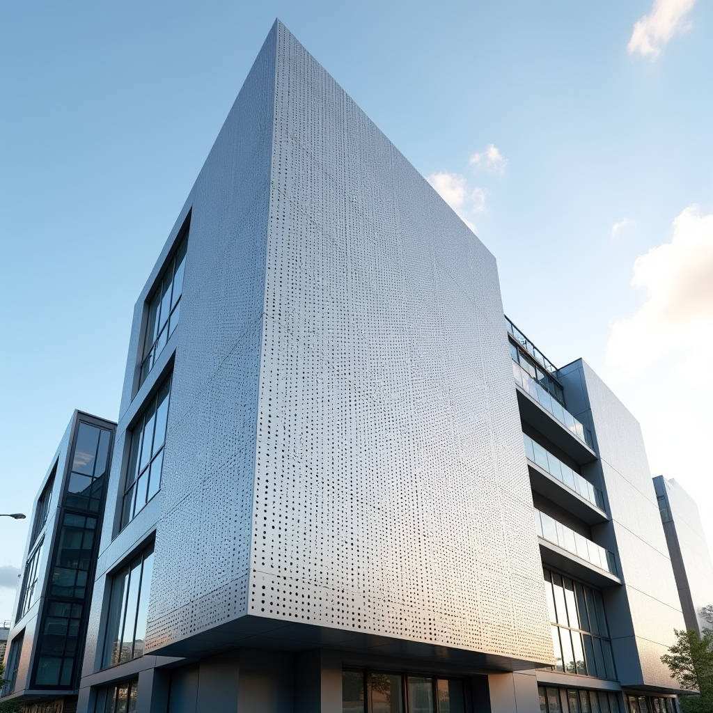
A perforated ventilated facade is a rainscreen system built from solid aluminium sheets that have been punched, drilled, or routed with a controlled open area, mounted with a continuous air cavity behind them. The perforations do two jobs at once: they break up solar gain and diffuse daylight while still allowing air to move through the cavity, which is what makes the assembly a true ventilated facade rather than a sealed skin. For general contractors and facade engineers, the practical question is rarely whether perforated aluminium works, but how to specify hole geometry, open-area ratio, and support framing so that the panel performs under wind load, resists fatigue, and stays flat across a long service life. This article works through those decisions from a fabrication and procurement standpoint, using solid aluminium sheet from 2.0 to 3.0 mm and PVDF-coated finishes as the baseline.
Why Perforation Changes the Structural Rules
A solid 3.0 mm aluminium panel behaves predictably under load. Punch a pattern into the same sheet and the effective section modulus drops, stress concentrates around each hole, and the panel deflects more for the same pressure. This is not a cosmetic detail; it drives panel size, stiffener layout, and the depth of the support system. The reduction in stiffness is roughly proportional to the open area, but the relationship is not linear at high perforation ratios because the remaining ligament width between holes becomes the controlling factor.
When a panel is specified with 40 percent open area, the remaining metal is a lattice of narrow ribs. Those ribs carry bending stress and, under repeated wind gusts, accumulate fatigue cycles. Aluminium alloy 3003 or 5005 in the H14 temper, which is standard for architectural sheet, has good fatigue behaviour for this application, but only if the hole edge condition is clean. A ragged punch edge or a burr acts as a crack initiation point. This is why reputable fabricators deburr every hole and why the specification should call out edge condition explicitly rather than leaving it to shop discretion.
Perforation is not a pattern choice first. It is a structural modification first, and the pattern follows from the engineering limits of the sheet.
Open-Area Ratio and Its Effect on Airflow
The ventilating function of a perforated ventilated facade depends on the open-area ratio, which is the percentage of the panel face that is actually open hole. A ratio below 15 percent still reads visually as a solid surface and provides only modest cavity ventilation. Between 20 and 40 percent, the facade begins to move meaningful air and shade the inner wall effectively. Above 50 percent, the panel becomes more screen than skin, and its structural capacity drops sharply, requiring heavier framing or smaller panel modules.
Airflow through the cavity is also governed by the size and spacing of the perforations, not just the total open area. Many small holes create more boundary-layer friction than fewer large holes at the same open-area ratio, so a 3 mm hole on a 6 mm staggered pitch moves air differently than a 10 mm hole on a 20 mm pitch. For a ventilated rainscreen intended to dry the cavity and reduce heat build-up, the target is a steady, low-velocity airflow rather than high volume. Designers should coordinate the hole pattern with the cavity depth and the vent openings at top and bottom of the facade, because the perforated face is only one part of the ventilation path.
Hole Geometry, Stagger, and Edge Distance
Round holes are the most economical to produce with turret punching and are the most forgiving structurally, because a circle distributes stress evenly around its perimeter. Square and slot perforations offer a different visual language but introduce sharp internal corners where stress concentrates. If a square or slot pattern is required for design reasons, the fabricator should radius the internal corners to at least 0.5 mm and the engineer should derate the panel stiffness accordingly.
Two layout parameters matter more than the hole shape itself: the stagger and the minimum edge distance. A 60-degree staggered pattern leaves more consistent ligament widths than a square grid, which improves flatness because the panel bends more uniformly. The minimum edge distance, measured from the hole centre to the panel edge, should be no less than 1.5 times the hole diameter for a punched panel and closer to 2 times for a routed or laser-cut panel, since the heat-affected or mechanically stressed zone near an edge is more prone to tearing during forming and handling.
Below is a reference table for common hole patterns in 3.0 mm solid aluminium sheet, showing how open area, ligament width, and typical maximum panel size interact. These figures assume a 60-degree stagger and a wind load of roughly 1.0 kPa, which covers many mid-rise applications.
| Hole Diameter (mm) | Pitch (mm) | Open Area (%) | Min. Ligament (mm) | Typical Max Panel (mm) |
|---|---|---|---|---|
| 3.0 | 6.0 | 23 | 3.0 | 1200 x 2400 |
| 5.0 | 9.0 | 28 | 4.0 | 1100 x 2200 |
| 8.0 | 14.0 | 30 | 6.0 | 1000 x 2000 |
| 10.0 | 16.0 | 35 | 6.0 | 900 x 1800 |
| 12.0 | 20.0 | 33 | 8.0 | 900 x 1800 |
These numbers are starting points, not a substitute for a panel-specific calculation. A project near the coast or in a high-rise condition will require a smaller module or a thicker sheet, and the fabricator should confirm the final pattern with a physical sample before full production.
Material, Thickness, and the Finish Question
Solid aluminium sheet for perforated ventilated facades is typically specified at 2.0, 2.5, or 3.0 mm. The 2.0 mm sheet is suitable for low open-area patterns and small modules, while 3.0 mm is the workhorse for larger panels and higher perforation ratios. Using a thicker sheet than strictly required is sometimes the cheaper overall solution, because it allows larger panels, fewer support rails, and fewer joints to seal and maintain.
Finish selection is more consequential on a perforated panel than on a solid one, because the hole walls are exposed. A coil-applied PVDF coating covers the flat face well, but the cut edges of each hole are bare aluminium unless the panel is post-coated after perforation. For a durable perforated ventilated facade, the specification should require a PVDF finish applied after punching, so that the coating wraps into the hole edges. The standard architectural PVDF system is a 70 percent PVDF resin content with a dry film thickness of 30 to 35 microns on a chromate conversion coat, meeting the performance criteria of AAMA 2605. This is the finish class that carries the long weather warranties expected on commercial cladding.
For coastal or industrial environments, a three-coat PVDF system or a thicker film on the hole edges provides additional protection, because the hole perimeter is where corrosion and filiform attack begin. Fabricators that can post-coat perforated sheet, rather than recoating pre-painted coil, deliver a measurably longer-lived panel. This is a point to verify in the factory audit rather than to assume from a datasheet.
Fabrication Tolerances That Matter on Site
Perforated panels are unforgiving of tolerance drift. A solid panel can hide a 1 mm discrepancy in a fold; a perforated panel with a visible hole grid will show any misalignment between adjacent panels immediately, because the eye tracks the pattern across the joint. The tolerances that matter in a perforated ventilated facade are therefore tighter than those in a standard rainscreen.
Panel flatness is the first concern. Perforation releases internal stress in the sheet and can cause oil-canning if the pattern is uneven or the sheet was not stress-relieved. The industry reference for flatness on architectural aluminium is often tied to The Aluminum Association flatness tolerances, but for perforated work a practical target is a maximum deviation of 2 mm per 1000 mm of panel length, checked with a straightedge. Hole position tolerance should be held to plus or minus 0.3 mm so that patterns align across a 10 mm joint.
The second concern is burr and edge condition, already noted for fatigue. The third is the consistency of the open area across the sheet, because a punch tool that wears during a long run will gradually produce smaller holes, changing both the appearance and the airflow. A fabricator that tracks tool wear and replaces punch dies on a schedule, rather than when they fail, will hold a more consistent panel.
Support Framing and the Cavity
A perforated ventilated facade needs the same rainscreen fundamentals as a solid one: a drained and back-ventilated cavity, a continuous air and water barrier on the inner wall, and a support grid that allows thermal movement. The perforated face changes two things. First, the open face admits driving rain into the cavity more readily, so the cavity depth and the drainage path at the base of the wall must be designed for wet conditions. Second, the reduced panel stiffness usually means the support rail spacing must close up, or the panel must be stiffened with a folded return or a bonded stiffener on the rear face.
Cavity depth between 38 and 100 mm is typical. A shallower cavity ventilates less and dries more slowly; a deeper cavity adds cost and depth to the facade zone. The vent openings at the top and bottom of the wall should be sized as a proportion of the perforated open area so that the cavity does not become a dead air space, which would defeat the purpose of the ventilated design.
Thermal movement is another planning item. Aluminium expands at roughly 0.024 mm per metre per degree Celsius. A 3-metre panel across a 50-degree temperature swing moves about 3.6 mm, which the fixing system must absorb without binding. Slotted fixings on one axis, with a fixed point to anchor the panel, are the standard approach, and the perforation pattern should not be relied upon to absorb this movement.
Cost Drivers and Procurement Logic
Perforated ventilated facade panels cost more than solid panels of the same size for three reasons: the punching or cutting operation itself, the post-coating step required to protect hole edges, and the higher scrap rate that comes from nesting patterns and rejecting sheets with tool-wear defects. The open-area ratio is the single largest cost lever, because it drives both machine time and the structural downgrade that forces smaller panels and more framing.
A useful procurement rule is to push the design toward the largest hole and pitch combination that still delivers the required visual and airflow performance, because fewer, larger holes punch faster and leave more metal for stiffness. A 10 mm hole on a 16 mm pitch is significantly cheaper to produce than a 3 mm hole on a 6 mm pitch at a similar open area, and it will hold flatness better. The trade-off is visual grain; the finer pattern reads as a smoother texture from a distance, which is often the architectural intent.
For projects that need a reliable supply of post-coated perforated solid aluminium sheet with consistent hole geometry, a fabricator such as Futeng® can be a useful reference point, particularly where the specification demands AAMA 2605 performance and tight flatness tolerances across a large panel run. The value is in the process control, not in the brand name.
Specifying Wind Load and Fatigue Correctly
The governing load case for a perforated ventilated facade is usually wind, and the governing failure mode is fatigue at the hole ligaments under repeated pressure cycles. A panel that passes a single static load test can still fail after years of gust cycles if the ligament width is near the minimum and the hole edges are not clean. The design approach is to calculate the effective section properties of the perforated sheet, apply the project wind pressure from the local code, and then check the stress range against the fatigue behaviour of the aluminium alloy.
For reference, aluminium alloy 3003-H14 has a tensile strength around 145 MPa and a yield strength near 125 MPa, while 5005-H14 is slightly higher. The allowable stress for a perforated panel is a fraction of these values once the stress concentration at the holes is applied. A stress concentration factor of 2.5 to 3.0 around a round hole is a reasonable starting assumption for preliminary sizing, which is why designers should not simply treat the net section area as if it were a solid sheet of reduced thickness. Standards such as The Aluminum Association design manual provide the section property and fatigue guidance that a facade engineer builds on.
Wind tunnel or code-based pressure coefficients should be derived for the specific building form, and the perforated face should not be assumed to shed wind the way a solid panel does. A perforated panel with 30 percent open area still carries a large share of the wind load, because the holes are small relative to the panel and the flow does not pass freely at building scale.
Daylight, Shading, and the Thermal Argument
The reason many architects pursue a perforated ventilated facade is the combined daylight and shading behaviour. The perforated screen cuts direct solar gain while still admitting diffuse light and views, and the ventilated cavity carries away heat that would otherwise soak into the inner wall. The open-area ratio is the main dial for this behaviour: a 20 percent open area shades aggressively and reads nearly solid, while a 40 percent open area admits more light and view but shades less.
The acoustic behaviour is a secondary but real benefit. A perforated face backed by an air cavity and an absorbent layer can act as a sound absorber, which is useful on buildings near roads or rail lines. The absorption peak depends on the hole diameter, open area, cavity depth, and the absorbent fill, so it must be tuned to the target frequency range rather than assumed. This is a specialist calculation, but it is one more reason to treat the perforation pattern as an engineered parameter instead of a purely visual one.
Field Verification and Handover
A perforated ventilated facade should be checked in the field for three things before handover: pattern alignment across joints, flatness under raking light, and the integrity of the hole-edge coating. Raking light reveals oil-canning that a head-on view hides, and it is the most honest way to judge whether the panel flatness specification was met. A fabricator that ships flat panels with clean edges and consistent hole positions makes the installer's job straightforward; a fabricator that does not will produce a facade that looks acceptable in photographs but fails under close inspection.
The maintenance story is also worth stating in the handover documentation. A PVDF post-coated perforated panel needs little more than periodic washing, but the hole edges are the first place to inspect for coating breakdown in aggressive environments. Documenting the coating system, the open-area ratio, and the hole pattern allows the owner to plan inspection and cleaning on a realistic cycle.
Practical Recommendations for the Specification
For a general contractor or facade engineer writing a specification for a perforated ventilated facade, the decisions that most affect cost, durability, and buildability can be reduced to a short list. Fix the open-area ratio early, because it drives everything downstream. Choose the largest hole and pitch that meets the visual and airflow targets. Specify post-coated PVDF to AAMA 2605 so the hole edges are protected, and require a minimum edge distance and a deburred edge condition in the fabrication section. Close up the support rail spacing to match the reduced panel stiffness, and size the cavity vents in proportion to the perforated open area.
Finally, require a physical sample panel before full production, and inspect it under raking light for flatness and across the joint for pattern alignment. A perforated ventilated facade is a system of interacting decisions, and the sample is the cheapest place to catch a mismatch between the pattern, the framing, and the finish. When those decisions are aligned, the result is a facade that ventilates, shades, and lasts, built from solid aluminium sheet that is specified and fabricated with the same discipline as any other engineered cladding.