Perforated Screen Facade Engineering for Solid Aluminium Cladding Panels
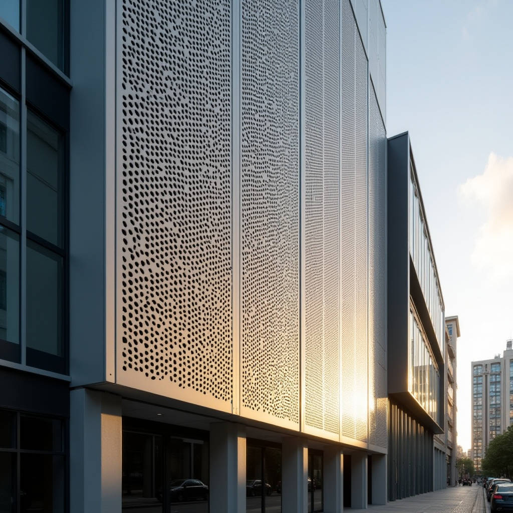
A perforated screen facade is rarely a decorative afterthought. In most commercial and institutional projects, the perforated solid aluminium panel is doing three jobs at once: cutting solar gain, managing daylight, and carrying wind load across a ventilated cavity. The engineering questions that decide whether the screen performs over a 25-year service life are not about pattern design. They are about open area ratio, panel thickness, perforation geometry, and the substructure that holds everything in place. This article works through the load path, the material limits, and the detailing decisions that separate a screen that stays flat and quiet from one that rattles, sags, or tears at its fixing points.
Why Open Area Ratio Drives Every Other Decision
The single most important number on a perforated screen facade drawing is the open area ratio (OAR), expressed as a percentage of void to total panel area. It is not a styling choice. OAR sets the solar heat gain coefficient of the screen, the wind pressure that passes through it, and the amount of solid material left to resist that pressure. A screen at 30% OAR has a very different structural behaviour from one at 55% OAR, even if both use the same 2.5mm solid aluminium sheet.
When a facade engineer specifies a perforated screen facade, the OAR is usually fixed early by the building physics model. A 35% OAR screen in front of a west-facing glazed wall can reduce direct solar radiation on the glass by roughly 25% to 35%, depending on perforation size and spacing. That reduction feeds directly into cooling load calculations and glazing selection. Change the OAR after the mechanical design is locked, and the whole facade performance envelope shifts.
The practical consequence for procurement is that OAR must be confirmed before panel pricing is finalised. More open area means less aluminium per square metre, but it also means more machining time, more scrap, and a weaker panel that may need a thicker sheet. The cheapest perforation is not the one with the most holes; it is the one that balances material, tooling, and structural reinforcement.
Perforation Geometry and the Stress Concentration Problem
Round holes are the workhorse of the perforated screen facade industry, and for good reason. A circular perforation distributes stress evenly around its edge, which keeps the local stress concentration factor low. Elongated slots, squares, and custom shapes concentrate stress at corners and narrow webs. A square hole punched into solid aluminium sheet will initiate fatigue cracking at its corners far earlier than a round hole of the same open area.
The governing rule in most perforation standards is the ligament, the strip of solid metal left between adjacent holes. As a general guide, the minimum ligament should not be less than the sheet thickness, and for panels carrying real wind load, a ligament of at least 1.5 times the material thickness is a safer starting point. When a designer pushes the ligament below the sheet thickness to achieve a lighter look, the panel begins to behave like a mesh rather than a plate, and its bending stiffness drops sharply.
Perforation method also changes the material. Turret punching work-hardens the edge of each hole and leaves a small burr that must be removed before coating. Laser and waterjet cutting produce cleaner edges but cost more per hole and are slower on large production runs. For a 2.0mm solid aluminium panel, turret punching is usually the economical choice up to a certain hole count per sheet, after which laser cutting becomes competitive. The crossover point depends on hole diameter and pitch, but a fabricator should be able to quote both methods so the project team can see the real cost difference.
Panel Thickness and Flatness After Perforation
Solid aluminium cladding panels for a perforated screen facade are typically specified at 2.0mm, 2.5mm, or 3.0mm. The choice is not arbitrary. Removing material to create perforations reduces the panel's effective section modulus, so a screen that looks flat on a 2.0mm sheet may oil-can badly once 40% of the metal is punched out.
Flatness after perforation is one of the most common complaints on site, and it is usually a specification problem, not a fabrication problem. Punching releases internal stress in the sheet, and the panel bows as that stress relaxes. A 2.0mm sheet with a dense perforation pattern will show more distortion than a 3.0mm sheet with the same pattern. For screens with an OAR above 40%, specifying 2.5mm or 3.0mm solid aluminium is often the difference between a flat facade and a visibly wavy one.
There is also a practical limit on panel size. A large-format perforated panel, say 1500mm by 3000mm, behaves very differently from a small infill panel. The larger the panel, the more it will deflect under its own weight and under wind load, and the more important it becomes to add stiffeners or to break the screen into smaller panels. Procurement teams should ask the fabricator for a deflection calculation at the specified design wind pressure before approving panel sizes.
Wind Load on a Perforated Screen: The Porosity Factor
A solid facade panel takes the full design wind pressure on its face. A perforated screen facade does not. Some of the wind passes through the holes, and the net pressure on the panel is reduced. The reduction is captured by a porosity factor, which is a function of the open area ratio. A screen at 30% OAR might carry only 60% to 70% of the pressure that a solid panel would carry at the same height and exposure. A screen at 50% OAR might carry less than half.
This sounds like good news, and for the panel itself it often is. But the wind that passes through the screen does not disappear. It pressurises the cavity behind the panel and acts on the inner wall or glazing. The substructure must also be designed for the pressure differential across the screen, not just the face load. A common failure is to design the support rails for the reduced face pressure while ignoring the cavity pressure build-up, which can load the fixings in a different direction.
When specifying a perforated screen facade in a high-wind region, the engineering team should request a wind study or at minimum a porosity-adjusted pressure calculation based on the project's design code. The relevant reference points include the wind load provisions of ASCE 7 in North America and the equivalent national annexes to Eurocode 1 elsewhere. Getting this number wrong is expensive: an under-designed screen will tear fixings, while an over-designed one wastes aluminium and money.
The Substructure and Fixing Detail
The aluminium skin of a perforated screen facade gets most of the attention, but the substructure is where long-term performance is decided. Perforated panels are lighter than solid panels of the same size, which tempts designers to reduce the support framing. That is a mistake. A perforated panel is less stiff than a solid panel of the same thickness, so it needs support points closer together to maintain flatness.
The typical support system is a vertical or horizontal carrier grid in aluminium, with the perforated panels fixed using either visible fasteners, concealed clips, or a cassette arrangement. Concealed systems look cleaner but are harder to align across a large perforated screen facade, because every panel edge must line up precisely for the pattern to read as continuous. Visible fasteners are more forgiving and easier to replace a single damaged panel, which matters on a screen that will be in service for decades.
Thermal movement is another detail that is easy to overlook. Solid aluminium expands and contracts with temperature, and a large perforated screen facade can move several millimetres between a cold night and a hot afternoon. Fixings must allow this movement without rattling or stressing the panel. Slotted holes, thermal breaks at the structural connection, and correctly sized expansion joints between panels are all part of a competent detail.
Coating Performance and Edge Coverage
A perforated screen facade exposes far more cut edge per square metre than a solid panel. Every hole has a circumference, and every circumference is a potential starting point for corrosion if the coating does not cover it properly. This is why coating specification for perforated panels is stricter than for solid sheet.
The industry benchmark is a PVDF fluoropolymer coating, typically applied as a two-coat or three-coat system with a total dry film thickness in the range of 25 to 35 microns for a two-coat system and up to 40 microns or more for a three-coat system. The key quality requirement is that the coating must wrap into the perforation edges. A panel that is coated before perforation will leave bare aluminium at every hole edge, which will oxidise and discolour within a few years. The correct sequence is to perforate first, deburr, pretreat, and then coat, so the paint reaches into each hole.
For coastal or industrial environments, a three-coat PVDF system or an enhanced pretreatment is worth the additional cost. The relevant performance standard is AAMA 2605 for superior-performance organic coatings on aluminium extrusions and panels. Specifiers should also check that the coating meets the colour and gloss retention requirements of the project's warranty period, which is typically 20 to 30 years for PVDF on architectural aluminium.
Cost Drivers and Real Project Numbers
Pricing a perforated screen facade is not a simple per-square-metre exercise. The cost is driven by the open area ratio, the perforation method, the panel thickness, the coating system, and the complexity of the substructure. A simple round-hole screen at 30% OAR on 2.5mm solid aluminium will cost substantially less than a custom-pattern screen at 50% OAR with concealed fixings on 3.0mm sheet.
The table below sets out indicative relative costs for a typical commercial project, using a 2.5mm solid aluminium panel as the baseline. These are planning figures for budgeting, not quotations, and they should be adjusted for project location and specification.
| Specification Variable | Baseline Option | Relative Cost Impact | Notes |
|---|---|---|---|
| Open area ratio | 30% round holes | 1.00 (baseline) | Higher OAR raises machining time and scrap |
| Open area ratio | 50% round holes | 1.25 to 1.40 | May require thicker sheet for flatness |
| Perforation method | Turret punch, round | 1.00 (baseline) | Economical for standard patterns |
| Perforation method | Laser or waterjet, custom | 1.30 to 1.80 | Cost rises with hole count and edge length |
| Panel thickness | 2.5mm solid aluminium | 1.00 (baseline) | Standard for medium OAR screens |
| Panel thickness | 3.0mm solid aluminium | 1.15 to 1.25 | Better flatness at high OAR |
| Coating system | Two-coat PVDF | 1.00 (baseline) | Standard architectural finish |
| Coating system | Three-coat PVDF | 1.08 to 1.15 | Recommended for coastal exposure |
| Fixing type | Visible fasteners | 1.00 (baseline) | Easier alignment and replacement |
| Fixing type | Concealed cassette | 1.15 to 1.30 | Tighter tolerances across full screen |
These numbers matter because a perforated screen facade is often value-engineered late in a project. Cutting the OAR or switching from a custom pattern to a standard round-hole layout can save real money without changing the architectural intent significantly. The earlier the fabricator is involved, the more of these trade-offs can be made before the design is frozen.
Fabrication Tolerances and Pattern Continuity
A perforated screen facade only looks precise when the pattern reads as continuous across panel joints. That requires a fabrication tolerance far tighter than a typical solid panel. If the perforation grid is off by even 1mm at a panel edge, the misalignment shows as a visible break in the pattern across the joint.
The practical way to manage this is to define the perforation pattern from a single datum on each panel and to specify a maximum deviation, commonly in the range of plus or minus 0.5mm for hole position. The fabricator should also control the edge-to-first-hole dimension so that adjacent panels match. On large screens, a full-size mock-up panel or a small test assembly is worth the cost, because it reveals pattern drift and edge alignment problems before production begins.
Handling and installation also affect pattern continuity. Perforated panels are more fragile than solid panels and can be dented or distorted if lifted incorrectly. Site storage should keep panels flat and protected, and installation crews should be briefed on the pattern direction so that panels are not flipped or rotated in a way that breaks the visual rhythm.
Acoustic and Environmental Considerations
A perforated screen facade is sometimes specified for acoustic reasons as well as visual and thermal ones. Perforated metal in front of an absorptive backing can act as a sound-absorbing system, reducing reflected noise in urban settings or around mechanical plant. The acoustic performance depends on the hole diameter, the open area ratio, and the depth of the cavity behind the panel, so it must be designed, not assumed.
There is also a maintenance dimension. Perforated panels collect less standing water than solid panels because rain drains through the holes, but the hole edges are more exposed to atmospheric pollutants. In a polluted or marine environment, the coating at the hole edges is the first place to fail, which is another reason to insist on perforate-then-coat sequencing and an adequate edge wrap.
For project teams working through these decisions, a fabricator with a controlled perforation and coating process can make the difference between a screen that is approved on the first mock-up and one that cycles through repeated resubmissions. Suppliers such as Futeng® who run perforation, pretreatment, and PVDF coating under one roof can shorten lead times and keep the pattern, coating, and flatness tolerances consistent from panel to panel. The value is in process control, not in any single material property.
Practical Engineering Checklist for Procurement
The decisions that determine the success of a perforated screen facade are made before the first panel is fabricated. A structured checklist keeps the specification coherent and prevents late-stage value engineering from undermining performance.
- Fix the open area ratio from the building physics model before pricing panels.
- Confirm the minimum ligament relative to sheet thickness for the chosen perforation shape.
- Select panel thickness based on post-perforation flatness, not on the unperforated sheet.
- Request a porosity-adjusted wind load calculation for the specific OAR and exposure.
- Design the substructure for cavity pressure as well as face load.
- Specify perforate-then-coat sequencing with adequate edge wrap on every hole.
- Define perforation position tolerance and edge-to-first-hole dimension for pattern continuity.
- Build a full-size mock-up or test assembly before production release.
A perforated screen facade is a system, not a skin. The panel, the coating, the substructure, and the fixing detail all have to work together across a 25-year service life. When the OAR, thickness, and coating are specified coherently, the screen delivers its solar, daylight, and wind performance without sagging, rattling, or corroding at the hole edges. When they are not, the problems show up early and cost far more to fix than they would have to specify correctly in the first place.
References for the engineering values discussed here include the wind load provisions of ASCE 7, the coating performance requirements of AAMA 2605, the material standards published by The Aluminum Association, and the European structural design framework of Eurocode 1. Project teams should always verify values against the governing code for the specific site.