Open Area Ratio and Wind Load Engineering for Perforated Metal Sheet Facade
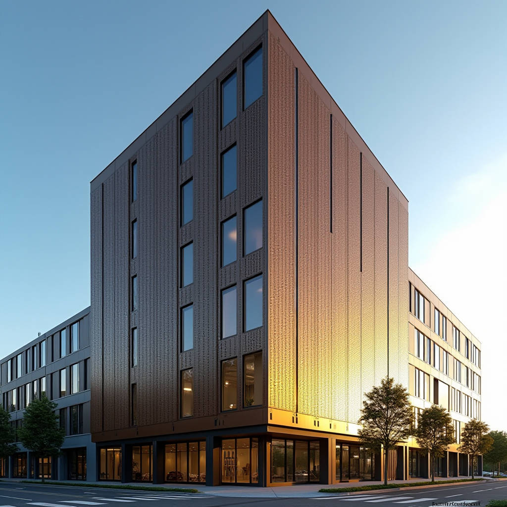
A perforated metal sheet facade is rarely understood as a structural system, yet the way a project team handles open area ratio, panel thickness, and subframe layout decides whether the building envelope performs or fails over a 20-year service life. Most specification errors on these facades do not come from the perforation pattern itself. They come from treating a perforated solid aluminium panel like a flat rainscreen and ignoring the drop in bending stiffness, the concentration of stress around each punched hole, and the wind load path that changes once the panel loses material. This article works through the load-bearing logic of a perforated metal sheet facade built from solid aluminium sheets, with the calculations, tolerances, and coating decisions that a facade engineer or procurement manager actually needs before signing off a shop drawing.
Why Perforation Changes the Structural Rules
A standard 3.0 mm solid aluminium rainscreen panel carries wind load across its full cross-section. Once that panel is perforated at a 40% open area ratio, the effective load-bearing section drops well below 60% of the original because the holes are not distributed evenly through the thickness. The material between adjacent holes acts as a series of narrow ligaments, and those ligaments carry concentrated stress at the hole edges. This is why a perforated metal sheet facade cannot be specified by copying the thickness of an adjacent solid facade panel.
The governing variable is the open area ratio, expressed as a percentage. A 20% open area facade behaves close to a solid panel and often works at 2.5 mm thickness. A 40% open area facade on a high-rise corner needs a step up to 3.0 mm solid aluminium, a reduced panel span, or an intermediate stiffener. A 50% or higher open area panel is closer to a screen than a rainscreen and should be treated as a purely visual layer with its own dedicated subframe, not as the primary weather barrier.
The second variable is hole geometry. Round holes in a staggered 60-degree layout distribute stress more evenly than square holes in a straight grid, because square holes create sharp corners where stress concentrates. Slot patterns, popular on parking structures, behave differently again: a horizontal slot weakens the panel in the vertical bending direction more than a vertical slot does. The pattern is not just an aesthetic choice. It is a structural input.
Wind Load and the Reduced Effective Section
Wind load calculations for a perforated metal sheet facade start from the same design pressure as a solid facade, typically derived from ASCE 7 in North America or EN 1991-1-4 in Europe. The difference is the structural capacity of the panel after perforation. A solid 3.0 mm aluminium sheet with a 600 mm span has a predictable allowable deflection. That same sheet perforated at 40% open area can lose 50% or more of its bending stiffness depending on hole spacing, because stiffness drops faster than the simple material removal percentage suggests.
A practical way to approach this is to treat the perforated panel as a plate with a reduced effective thickness rather than a reduced width. Engineers often back-calculate an equivalent solid thickness that produces the same deflection under the same load, then check that the resulting stress in the ligaments stays below the allowable fatigue and yield limits for the aluminium alloy. For a 3003-H14 or 5005-H14 solid aluminium sheet, the ligament stress at the edge of a punched hole can be two to three times the nominal panel stress, which is why the hole edge condition matters so much.
The subframe behind the panel is equally important. Perforated panels weigh less, so some contractors assume lighter framing is acceptable. The opposite is usually true. Because the panel is less stiff, the subframe must pick up the same wind load with shorter spans and more attachment points. A perforated metal sheet facade that looks light on the surface often carries a denser, more expensive support grid than the solid facade next to it. Procurement teams that budget only for the perforated sheet and ignore the framing increase are the ones that end up with change orders.
Open Area Ratio and Its Knock-On Effects
Open area ratio is the single number that drives almost every downstream decision on a perforated metal sheet facade. It determines structural capacity, as covered above, but it also controls daylight, ventilation, acoustic behaviour, and the visibility of the cavity behind the panel. A 25% open area facade reads as a solid surface from a distance with a subtle texture. A 45% open area facade becomes transparent enough that the substructure, insulation colour, and any services behind the panel become visible, which means the design team has to detail the cavity as carefully as the face.
Acoustic performance cuts the other way. Higher open area lets sound pass through, which can be a benefit on a parking garage that needs natural ventilation or a problem on a facade facing a busy road. There is no universal optimum. The ratio has to be matched to the building's function first and the visual intent second.
The table below summarises how open area ratio changes the key engineering parameters for a solid aluminium perforated panel, assuming a 3.0 mm sheet and a typical 600 mm vertical span. These are design guidance figures, not a substitute for project-specific calculations.
| Open Area Ratio | Typical Application | Stiffness Retention (approx.) | Recommended Panel Thickness | Subframe Span Adjustment |
|---|---|---|---|---|
| 10–20% | Decorative rainscreen, subtle texture | 70–85% | 2.5–3.0 mm | Minimal change vs solid |
| 25–35% | Balanced solar shading and screening | 50–70% | 3.0 mm | 10–20% shorter spans |
| 40–50% | Parking screens, ventilation facades | 30–50% | 3.0 mm + stiffeners | 20–35% shorter spans |
| Above 50% | Visual screen layer only | Below 30% | 3.0 mm + dedicated subframe | Independent support grid |
Punching Method and Hole Edge Quality
The way holes are produced in a solid aluminium sheet determines both the fatigue life and the appearance of a perforated metal sheet facade. CNC turret punching and full-width die punching are the two common industrial routes. Turret punching is flexible and suits small runs or complex mixed patterns, but it leaves a slightly deformed edge and can introduce micro-burrs. Die punching produces a cleaner, more consistent hole with a smoother edge, but the tooling cost only makes sense for large, repetitive runs.
The hole edge is the stress concentration point, so a clean, deburred edge is not a cosmetic nicety. It is a durability requirement. A ragged edge from worn tooling creates a notch that can initiate cracking under repeated wind cycling, especially on panels with a 40% or higher open area ratio. This is one reason why a perforated metal sheet facade should be punched before forming and coating, so that the coating can wrap and seal the hole edges rather than leaving raw aluminium exposed.
There is also a flatness consideration. Punching releases internal stress in the sheet and can cause the panel to bow. A fabricator that punches a large sheet and then forms the return legs without a flattening step will deliver panels that ripple in sunlight. The best fabricators punch, flatten, then form, and finally check flatness against a straight edge before coating. This sequence sounds obvious, but it is exactly where short-run suppliers cut corners.
Coating a Perforated Surface Correctly
Coating a perforated metal sheet facade is more demanding than coating a solid panel because the edges of every hole must be covered, not just the flat faces. A PVDF fluoropolymer coating is the standard for exterior solid aluminium panels, and the specification should call for a minimum total dry film thickness of 30–35 microns on the exposed face, applied as a primer plus colour coat, with the option of a clear topcoat for coastal or high-UV environments. The coating must be applied so that it wraps into each hole edge, which requires a spray line that can reach the interior of the perforation rather than a flat-line coater that only hits the surface.
The colour choice interacts with the perforation. Dark colours absorb more solar heat, and on a perforated panel the heat is concentrated in the thin ligaments between holes. This raises the surface temperature and accelerates coating breakdown if the film thickness is marginal. A dark bronze or black perforated metal sheet facade in a hot climate should be specified with a thicker film and a heat-reflective clear coat, or the design team should accept a lighter colour to reduce thermal stress.
AAMA 2605 is the performance specification most facade engineers reference for high-performance PVDF coatings on aluminium, and it sets out the weathering, colour retention, and film integrity requirements that a coating must meet for a long exterior life. Aligning the coating specification with AAMA 2605 gives the procurement team a defensible standard to hold the fabricator to, rather than relying on a vague "PVDF coating" line item.
Alloy, Thickness and the Solid Aluminium Difference
The base material for a perforated metal sheet facade should be a solid aluminium sheet in the 3000 or 5000 series. Alloy 3003 offers good formability and is widely used for flat and lightly curved panels. Alloy 5005 provides better corrosion resistance and a more uniform anodised or coated finish, which matters when the perforation exposes more edge surface to the weather. Both are available in the 2.0 mm, 2.5 mm and 3.0 mm thicknesses that cover most perforated facade applications.
The material standard to specify is ASTM B209, which covers aluminium and aluminium-alloy sheet and plate. Referencing this standard in the specification ensures the panel is genuine solid aluminium sheet with the correct temper, not a thinner or lower-grade substitution. The temper designation, such as H14, matters because it fixes the strength and formability of the material, and a perforated panel needs a temper that balances both.
Suppliers such as Futeng® work with solid aluminium sheet precisely because perforation demands a material that behaves predictably when material is removed. The punch tooling, the coating line, and the flatness control are all tuned to a consistent base sheet, and that consistency is what lets a fabricator hold the tight hole-to-hole tolerance that a perforated metal sheet facade requires across hundreds of panels.
Tolerances That Actually Matter on Site
A perforated metal sheet facade lives or dies on alignment. Because the pattern repeats across the elevation, a small error in hole pitch or panel width becomes visible as a break in the rhythm, often from across the street. The tolerances that matter are hole diameter, hole pitch, panel edge-to-first-hole distance, and panel flatness.
Hole diameter should be held to plus or minus 0.2 mm for punched holes in the 5 mm to 20 mm range. Hole pitch, the centre-to-centre distance, should be held to plus or minus 0.3 mm across a panel. The edge margin, the distance from the panel edge to the first row of holes, is the detail most often missed, because a panel that is trimmed after punching can end up with a different edge margin on each side, breaking the visual continuity at the joint.
Panel flatness after coating should be checked against a tolerance of about 0.5% of the panel dimension, which for a 1200 mm panel is roughly 6 mm of allowable deviation. Tighter flatness is achievable but costs more, and it is usually only worth specifying on a perforated metal sheet facade with a very low open area ratio where ripples show up clearly in raking light.
Acoustic and Daylight Trade-Offs
The open area ratio of a perforated metal sheet facade directly sets its acoustic and daylight behaviour. Sound passes through the holes, so a high open area facade provides little airborne sound insulation unless the cavity behind it is filled or the inner wall is closed. This is why perforated facades on offices and hotels are often used as a second skin over a glazed or solid inner wall, where the perforated layer handles shading and visual screening while the inner layer handles acoustics and weather.
Daylight control is the more common driver. A perforated metal sheet facade with a 30% to 40% open area ratio can cut direct solar gain significantly while still allowing diffuse light into the building, reducing cooling load and glare at the same time. The exact performance depends on the hole size, spacing, and the angle of incidence, so a pattern that performs well in one orientation may underperform on another facade of the same building. Orientation-specific pattern design is the difference between a facade that works and one that only looks perforated.
For projects where acoustic or solar performance is a contractual requirement, the design team should reference the relevant test standards early. The ISO 10140 series covers laboratory measurement of sound insulation, while solar performance is typically modelled against site-specific data. Getting these numbers locked before fabrication avoids the situation where a visually approved pattern fails a performance test late in the programme.
Cost Drivers Beyond the Sheet Price
Procurement teams often anchor the budget of a perforated metal sheet facade to the cost per square metre of the perforated sheet alone. That number is the smallest part of the total installed cost. The real cost drivers are the open area ratio, the hole geometry, the subframe density, and the coating specification.
A higher open area ratio reduces the weight of aluminium per panel but increases the punching time and the scrap rate, so the material saving is partly offset. Complex patterns with mixed hole sizes or a non-repeating layout cost more to programme and punch than a uniform staggered grid. The subframe cost rises as the panel stiffness falls, because shorter spans mean more brackets, more rails, and more fixings.
The coating specification is the quiet cost driver. A standard two-coat PVDF system is the baseline. Adding a clear topcoat for a coastal site, or specifying a thicker film for a dark colour, adds a meaningful percentage to the coating cost and to the lead time. Understanding these trade-offs before the tender stage lets a procurement team compare fabricator quotes on a like-for-like basis instead of being surprised by the detail.
Specifying the Subframe and Fixings
The subframe behind a perforated metal sheet facade carries the same wind load as a solid facade but with a less stiff panel in front of it. The rails and brackets should be aluminium of a compatible alloy to avoid galvanic corrosion, and the fixings should be stainless steel or aluminium. The fixing pattern must account for the fact that the panel is weaker between holes, so fixings should be located in the solid margins of the panel rather than immediately adjacent to a punched hole.
Thermal movement is another detail. Aluminium expands and contracts with temperature, and a perforated panel has less continuous metal to absorb that movement. A perforated metal sheet facade on a south-facing elevation can see surface temperatures swing by 60 degrees Celsius or more between winter night and summer afternoon, and the fixing system must allow for that movement without rattling or binding. Slotted holes and flexible clips are the standard answer, and the engineering guide from the Aluminum Association is a useful reference for thermal movement design.
The joint between panels is also a design decision. A perforated metal sheet facade can use open joints, which allow air and some water through and require a drained cavity behind, or closed joints with gaskets, which add cost and complexity but provide a more controlled cavity. Open joints are the more common choice for perforated facades because they are simpler and the perforation already allows air movement, but the cavity detailing, drainage, and ventilation must be resolved in the shop drawings.
Quality Control Before the Panels Ship
The inspection points that catch problems on a perforated metal sheet facade are predictable. First, check the hole pattern against the approved sample, because the pattern is the first thing anyone sees. Second, check the hole edges under magnification for burrs and coating coverage, because that is where premature failure starts. Third, check flatness against the tolerance, because ripples are the first complaint after installation. Fourth, check the edge margin consistency, because that is the detail that breaks the visual rhythm at the joints.
A pre-production sample panel, coated in the final colour and punched with the final tooling, is the single most valuable quality control document on a perforated metal sheet facade. It locks the appearance, the hole quality, the coating thickness, and the flatness in a physical object that both the fabricator and the client sign off. Without it, disputes over what "matches the approved pattern" means are almost guaranteed.
The installation sequence matters too. Perforated panels are light enough that handling damage is common, and a dented or bent panel cannot be repaired invisibly because the hole pattern will never line up again. Panels should be handled vertically, stored flat on protected racks, and installed with suction lifters or padded clamps rather than straps that can crease the edges.
A Practical Specification Checklist
A perforated metal sheet facade specification that survives contact with the tender process needs to pin down the following points. Each one is a place where ambiguity turns into cost or a failed inspection.
- Base material: solid aluminium sheet to ASTM B209, alloy 3003-H14 or 5005-H14, 2.5 mm or 3.0 mm as calculated.
- Open area ratio and hole geometry, with the pattern drawing attached to the specification.
- Coating: PVDF to AAMA 2605, minimum dry film thickness stated, edge coverage required.
- Tolerances for hole diameter, pitch, edge margin, and flatness.
- Subframe alloy, fixing type, and thermal movement allowance.
- Pre-production sample panel approval before full fabrication.
- Wind load design pressure and the deflection limit the panel must meet.
A specification that covers these points gives the fabricator enough to quote accurately and the site team enough to inspect against. A specification that skips them leaves the open area ratio, the coating thickness, and the subframe span to be argued about after the panels are already in production, which is the most expensive place to resolve a facade decision.
The engineering logic of a perforated metal sheet facade comes down to treating the holes as a structural input rather than a decoration. Open area ratio drives stiffness, which drives thickness and subframe span. Hole edge quality drives durability. Coating coverage drives corrosion resistance. When those four variables are resolved together, a perforated solid aluminium facade delivers the visual lightness the architect wants with the service life the owner is paying for.