Perforated Metal Facade Detail Cut Edge Coating and Wind Load Decisions for Solid Aluminium Panels
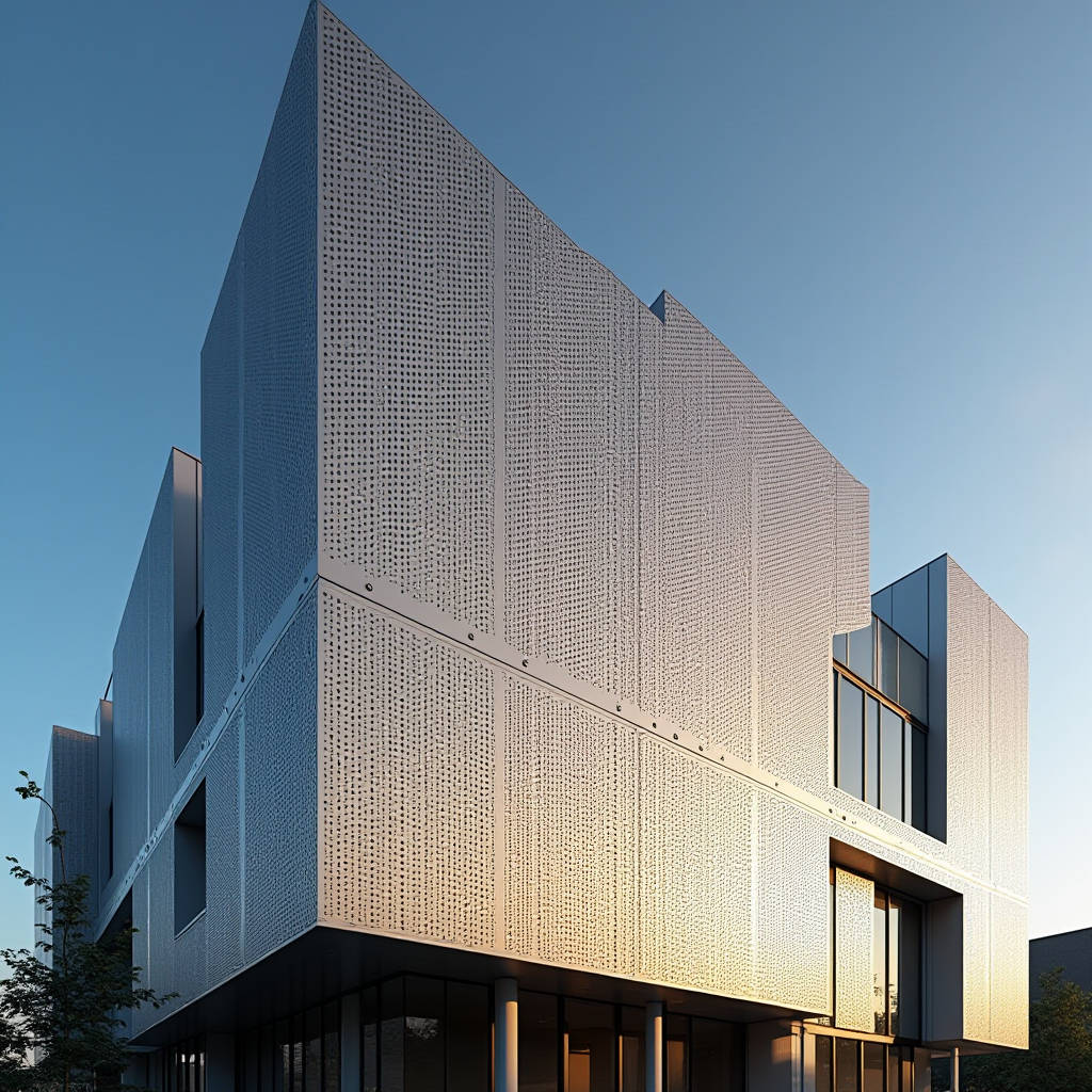
When a facade engineer or procurement manager asks about a perforated metal facade detail, the question is rarely about the panel itself. It is about the hidden decisions that determine whether a perforated skin performs for twenty years or becomes a warranty claim within two. A perforated metal facade detail is the sum of several interdependent choices: open area ratio, hole geometry, material thickness, finish system, and the substructure that carries wind and thermal movement. Get any one of these wrong and the pattern loses its visual rhythm, the panel oil-cans in the afternoon sun, or the coating fails at the cut edge. This article works through those decisions in the order they actually happen on a project, using solid aluminium cladding panels as the reference material and giving you numbers you can check against your own shop drawings.
Why the Perforation Pattern Is an Engineering Decision First
Most perforated facades start as a visual idea: a gradient of holes, a repeating motif, a pixelated image. The first technical reality is that every hole removes aluminium that was carrying load. A panel with 40% open area has only 60% of its original cross-section resisting bending at any given line. This changes the effective stiffness of the panel and, more importantly, shifts where the panel wants to deflect under wind load.
For solid aluminium cladding panels in the 2.0 mm to 3.0 mm thickness range, the relationship between open area and panel flatness is predictable but not linear. A 2.0 mm panel at 25% open area will generally hold its plane across a 600 mm x 600 mm module with a standard perimeter tray return. Push the same panel to 45% open area and you either need to step up to 2.5 mm or 3.0 mm material, reduce the module size, or add intermediate stiffeners. The stiffener is the cheaper fix on paper and the more expensive fix in the field, because every stiffener adds a visible shadow line and a potential point of corrosion if not bonded correctly.
The hole geometry matters as much as the open area percentage. Round holes are the most forgiving because stress concentrates evenly around a circle. Slot, square, and custom shapes create stress risers at the corners, which is where fatigue cracks and coating delamination begin. If the design demands square or rectangular perforations, the corner radius becomes a specification item, not a detail to be sorted out in fabrication.
Open Area, Hole Size, and the Visual Density Trap
Architects tend to specify perforation by open area percentage, but two panels can both be 30% open and look completely different. A 30% open area made of 8 mm holes on a 12 mm pitch reads as a fine mesh from street level. The same 30% open area made of 25 mm holes on a 40 mm pitch reads as a bold, graphic screen. The difference is hole count and edge density, and it drives cost in opposite directions.
Fine perforation means more holes per square meter, which means more machine time and more tooling wear. It also means more cut edge per panel, and cut edge is where a coating system is most vulnerable. A panel with 8 mm holes at 30% open area has roughly four times the cut-edge length of a panel with 25 mm holes at the same open area. That is four times the surface area where the aluminium substrate is exposed unless the coating process is sequenced correctly.
The practical guidance for procurement is to treat hole size and open area as two separate specification lines, not one. Ask the fabricator for the cut-edge length per square meter, not just the open area. A reputable supplier such as Futeng® will provide this figure in the fabrication schedule because it directly affects both the coating warranty and the price.
Coating the Cut Edge Is Where Most Perforated Facades Fail
A solid aluminium cladding panel is typically coated with PVDF fluoropolymer before perforation on many production lines. The problem is obvious: perforating a pre-coated panel exposes raw aluminium at every hole wall. If that edge is left bare, the aluminium oxidises, the oxide creeps under the coating, and within a few seasons you see a white or grey halo around every hole. This is the single most common warranty issue on perforated facades.
There are two defensible sequencing approaches. The first is to perforate first, then coat the entire panel including the hole interiors. This gives the best edge protection but requires a coating line that can pull the coating into small holes without clogging them. For holes below 10 mm, coating after perforation can change the effective hole diameter by 0.1 mm to 0.2 mm, which matters when the pattern tolerance is tight. The second approach is to coat first, then perforate, then apply a secondary edge treatment such as a clear chromate conversion or a touch-up coating. This is faster and cheaper but relies on field discipline and rarely carries the same warranty length.
The ASTM and AAMA standards frame this clearly. AAMA 2605 governs the performance of the PVDF coating itself, but the cut-edge protection is a process specification, not a coating specification. When you review a perforated metal facade detail, the fabrication sequence should be stated explicitly in the drawing notes: perforate-then-coat or coat-then-perforate-with-edge-treatment. If the sequence is not stated, the detail is incomplete.
Wind Load, Stiffness, and the Substructure Behind the Pattern
Perforated panels behave differently in wind than solid panels, and not in the way most people assume. The holes do reduce the total pressure on the panel, but only partially. A panel with 30% open area does not see 30% less wind load; the actual reduction depends on hole size, wind speed, and whether air can pass through the cavity behind the panel. If the panel is installed tight against a solid wall with no cavity ventilation, the perforation creates a complex pressure condition that can actually increase local suction in some zones.
The conservative engineering approach is to calculate wind load on the solid panel area and apply a reduction factor that accounts for the open area and the cavity condition. Many facade engineers use a reduction factor of roughly 0.7 to 0.9 for perforated panels with open areas between 20% and 40%, but this should come from a wind tunnel study or a recognised code reference, not a rule of thumb. The ASCE 7 wind load provisions provide the base pressures, and the perforation reduction is then a project-specific adjustment.
The substructure question follows directly. A perforated panel has less bending capacity than a solid panel of the same thickness, so the supporting frame must either carry more of the load or be spaced more tightly. The two common strategies are a welded steel or aluminium subframe with panel clips, or a cassette system where the perforated panel is formed with deep returns that act as integral stiffeners. The cassette route is often the better value on a perforated metal facade detail because the return depth does the work of a stiffener without adding a separate member.
Thermal movement is the other substructure consideration. Aluminium expands and contracts at roughly 0.024 mm per meter per degree Celsius. A dark-coloured perforated panel in full sun can reach 70°C to 80°C on the surface, while the supporting steel behind it stays much cooler. The differential movement between a 3 m aluminium panel and its steel frame over a 50°C swing is in the range of 3 mm to 4 mm. If the fixing detail does not allow for this, the panel will buckle or the fixings will work loose. Slotted holes and a floating clip system are not optional on large perforated panels; they are the detail.
Finish System Selection for Perforated Aluminium
PVDF is the default finish for exterior solid aluminium cladding panels, and for good reason. A properly applied PVDF coating meeting AAMA 2605 will hold colour and gloss for well over a decade in most climates. But perforation introduces two factors that change the finish conversation: cut-edge exposure and the visual role of the panel.
When the perforated panel is a screen in front of a glazed or insulated wall, the back face of the panel is visible through the holes. This means both faces need the same finish quality, not just the weather face. Many specifications only call for a single-face coating, which leaves the back face with a thin wash coat that reads as a different colour through the perforation. A perforated metal facade detail should state a two-coat minimum on the back face, and ideally a full three-coat PVDF on both faces for panels with open areas above 30%.
The table below compares the finish options that realistically apply to perforated solid aluminium panels, with the parameters that matter most when the cut edge is in play.
| Finish System | Typical Dry Film Thickness | Cut-Edge Protection | Colour / Gloss Retention | Best Application |
|---|---|---|---|---|
| PVDF 3-coat (AAMA 2605) | 30-35 µm | Good if perforate-then-coat | Excellent, 10-20 yr | High-end exterior screen, both faces visible |
| PVDF 2-coat (AAMA 2604) | 25-30 µm | Moderate, edge treatment advised | Very good, 5-10 yr | Standard exterior, one visible face |
| Polyester powder coat | 60-80 µm | Good edge wrap if applied after perforation | Moderate, 3-5 yr exterior | Interior or sheltered applications |
| Anodised finish | 10-25 µm oxide layer | Edge is anodised if processed after perforation | Good, but limited colour range | Natural metallic look, low-maintenance |
The dry film thickness figures above follow the AAMA specification framework for architectural coatings on aluminium, and they assume a solid aluminium substrate rather than a composite core. This distinction matters because the edge of a solid panel behaves differently from a laminated edge, and the coating adhesion at a cut edge is a function of the substrate preparation, not just the coating chemistry.
Fabrication Tolerances and the Pattern Alignment Problem
A perforated metal facade detail lives or dies on tolerance. The hole pattern must align across panel joints, around corners, and against adjacent building elements. If the pattern shifts by 3 mm at a panel joint, the eye catches it immediately, even from across the street. This is why the fabrication tolerance and the installation tolerance have to be designed together, not separately.
For a CNC-punched or turret-punched solid aluminium panel, the hole position tolerance is typically ±0.1 mm to ±0.2 mm relative to the panel datum. The panel cut size tolerance is usually ±0.5 mm to ±1.0 mm. The problem is the joint: if two adjacent panels are each within tolerance but the joint gap varies by 2 mm, the pattern appears to jump. The standard fix is to establish a continuous datum line across the facade and to reference every panel's perforation to that datum, not to the panel edge. This is a shop drawing discipline, and it is worth confirming before panels are in production.
Corner conditions deserve their own note. When a perforated pattern wraps a corner, the hole spacing must be adjusted so that the pattern appears continuous through the bend. This usually means the flat pattern is developed with the bend allowance calculated into the hole layout, which is a different exercise from simply punching a flat sheet and then folding it. The ISO 2768 general tolerance framework is a useful reference for the non-perforation dimensions, but the pattern alignment itself should be a project-specific tolerance schedule.
Cost Drivers You Can Control at the Specification Stage
Perforated aluminium is more expensive than solid sheet, but the cost is not evenly distributed. The three biggest drivers are open area, hole size, and finish sequencing, and all three are decided at the specification stage, long before a fabricator quotes.
Open area drives material yield. A 40% open area panel produces 40% scrap by weight from the punching process, and that scrap aluminium has a recovery value but not a full one. The scrap value of punched aluminium is typically 40% to 60% of the ingot price, so the net material cost of a 40% open area panel is higher than a simple area calculation suggests.
Hole size drives machine time. Fine perforation at 8 mm or below requires slower feed rates and more frequent tool changes, and it can double or triple the punching time per panel compared to a 20 mm pattern. If the design allows a hole size of 12 mm or larger, the fabrication cost drops noticeably with no loss of visual impact at typical viewing distances.
Finish sequencing drives warranty and price together. Perforate-then-coat is the more expensive process because the coating line must be set up to handle pre-perforated sheets, which are more fragile and harder to handle. But it is also the process that carries the longer warranty, because the cut edge is fully protected. The cost difference between the two sequences is commonly 10% to 20% of the finish cost, and it is money well spent on an exterior screen in a coastal or industrial environment.
A realistic budget figure for a perforated solid aluminium cladding panel, supplied and installed, runs from roughly USD 180 to USD 380 per square meter depending on open area, hole size, finish, and substructure complexity. This is a wide range because the variables above swing the number hard in either direction. The point is not the specific figure but the fact that the specification choices, not the market, set most of the range.
Specifying the Detail So the Built Facade Matches the Render
The gap between a beautiful render and a built perforated facade is almost always a series of unspecified details. The render shows a perfect gradient of holes; the built panel shows a visible joint every 1.2 m. The render shows a uniform colour; the built panel shows a halo around every hole because the edge was never protected. The render ignores the substructure; the built facade shows a shadow grid behind the screen.
A complete perforated metal facade detail specification should carry at least these lines: material and temper of the solid aluminium sheet, panel thickness, open area percentage, hole geometry with corner radius, cut-edge length per square meter, finish system with film thickness on both faces, fabrication sequence for coating relative to perforation, pattern datum and alignment tolerance, fixing method with thermal movement allowance, and the wind load reduction factor used in the structural calculation. If any of these lines is missing, the detail is not yet ready for tender.
The ISO 9001 quality framework is a useful reference when auditing a fabricator's process control, but the specification itself is the document that protects the project. The more precisely the detail is written, the less room there is for a fabricator to make an assumption that shows up later as a defect.
Engineering Judgement on the Detail That Matters Most
If there is a single detail to get right on a perforated metal facade, it is the cut edge. The pattern, the open area, and the substructure are all visible and get attention in design review. The cut edge is invisible in the render and in the first year of service, and then it becomes the most visible thing on the building. A perforated panel with unprotected edges will show oxidation around every hole within two to five years in a humid or coastal climate, and the repair is not a touch-up; it is a full panel replacement.
The second detail is the thermal movement allowance. Perforated panels are often larger than solid panels of the same thickness because the holes reduce weight, and larger panels move more. A fixing detail that works on a 1.2 m solid panel will bind on a 2.4 m perforated panel. The slotted hole, the floating clip, and the expansion joint at the panel boundary are not refinements; they are the difference between a facade that stays flat and one that buckles in its first hot summer.
The third detail is the finish on the back face. It is easy to overlook because the back face is hidden in the drawing, but on a perforated screen the back face is visible through every hole. A two-face specification is the standard for any perforated panel with open area above roughly 25%, and it should be written as a finish requirement, not left as a note.
For the procurement team, the practical move is to insist on a fabrication sequence and a tolerance schedule in the quotation, not just a price per square meter. The price without the sequence tells you nothing about the warranty you are actually buying. A supplier that can state the perforate-then-coat sequence, the cut-edge length, and the pattern datum in the first round of pricing is a supplier that understands the detail, and that understanding is worth more than a lower number on a line item.