Perforated Metal Cladding Detail Engineering For Structural Integrity And Ventilation
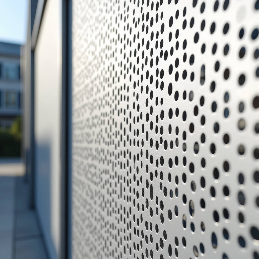
Achieving a successful facade installation begins with understanding that every perforated metal cladding detail directly influences both aesthetic performance and long-term structural safety. Unlike standard solid panels, perforated sheets introduce complex stress concentrations and reduced cross-sectional areas that demand rigorous engineering validation before fabrication. Architects and contractors must evaluate open area percentages alongside specific alloy temper selections to prevent panel distortion under negative wind suction. This technical analysis ensures the perforated metal cladding detail functions as a durable building envelope component rather than merely a decorative screen. Proper detailing accounts for thermal expansion differentials, coating adhesion on cut edges, and precise subframe connections to guarantee the system meets international safety standards while delivering the intended visual transparency and ventilation benefits required by modern architectural specifications.
Structural Implications Of Open Area Ratios In Solid Aluminium Panels
The relationship between perforation density and structural capacity is the most critical factor in facade engineering. When specifying a perforated metal cladding detail, the open area ratio fundamentally alters the moment of inertia and section modulus of the base material. A common misconception is that 3mm solid aluminium retains its full load-bearing capacity regardless of hole patterns. In reality, a 40% open area reduces the effective structural cross-section significantly, requiring compensatory measures. Engineering calculations must reference ASTM B209 specifications for aluminium sheet properties, adjusting allowable stress values based on the net section remaining after punching.
For solid aluminium panels ranging from 2.0mm to 3.0mm thickness, the maximum unsupported span decreases non-linearly as perforation density increases. A 2.5mm panel with 15% open area may safely span 600mm between supports under 1.5 kPa wind load, whereas the same panel with 45% open area might require reducing spans to 350mm or adding intermediate stiffeners. These calculations prevent oil-canning effects and permanent deformation during extreme weather events. Contractors should request certified structural calculations from manufacturers that specifically account for the weakened sections created by the perforation pattern, rather than relying on generic solid panel span tables.
Alloy Selection And Temper Designations For Perforated Applications
Material selection becomes more restrictive when implementing intricate perforated metal cladding detail work. While AA1100 offers excellent formability for complex shapes, it lacks the tensile strength necessary for large-format perforated facades in high-wind zones. AA3003-H14 or H24 temper provides the optimal balance of strength and ductility for most architectural applications involving solid aluminium sheets. The H14 designation indicates strain-hardened condition suitable for flat panel applications where moderate forming occurs during edge folding and stiffener attachment.
For projects demanding higher yield strength due to extreme perforation densities or larger module sizes, AA5005-H34 serves as a superior alternative. This magnesium-alloyed variant maintains better corrosion resistance in marine environments while offering approximately 20% higher tensile strength compared to 3003 series. However, increased hardness can lead to micro-cracking at hole edges during CNC punching if tooling clearances are not precisely calibrated. Fabricators must adjust punch-to-die ratios according to material temper to ensure clean hole edges without burrs that could compromise subsequent PVDF coating application or create moisture retention points.
Reinforcement Strategies And Stiffener Integration Details
Integrating rear reinforcement represents the primary method for restoring rigidity to perforated solid aluminium panels. The perforated metal cladding detail must specify stiffener type, spacing, and attachment methodology to avoid visible telegraphing on the exposed face. Welded aluminium studs provide rigid connection points but introduce heat-affected zones that may cause localized warping on thin gauge materials. Structural adhesive bonding combined with mechanical fasteners often yields superior flatness results for perforated applications where thermal distortion must be minimized.
Stiffener profiles typically utilize extruded aluminium angles or formed channels ranging from 25mm to 50mm depth depending on calculated deflection limits. Spacing should align with perforation pattern modules where possible to maintain consistent visual rhythm and avoid stiffeners appearing through semi-transparent areas. At panel perimeters, continuous edge extrusions create robust framing that distributes point loads from fixing brackets across the entire panel width. This perimeter reinforcement is essential because hole patterns near edges create stress risers that concentrate forces at connection points. Engineering drawings should clearly indicate reinforced zones and prohibit perforations within 20mm of fold lines or stiffener attachment locations to preserve structural continuity.
Thermal Movement Accommodation In Perforated Systems
Solid aluminium expands and contracts at approximately 23.4 µm/m·K, creating significant dimensional changes across large facade areas. Perforated panels exhibit slightly different thermal behavior compared to solid sheets due to reduced mass and altered stiffness distribution. The perforated metal cladding detail must incorporate slotted holes at fixed connection points to allow unrestricted movement along the primary expansion axis. Fixed-point connections should be centralized on each panel with sliding connections positioned symmetrically outward to distribute movement evenly.
Calculating required slot length involves multiplying the panel dimension by the temperature differential range and the coefficient of thermal expansion, then adding minimum clearance tolerances. For a 1500mm wide panel experiencing 60°C seasonal variation, theoretical movement equals approximately 2.1mm. Practical slot design should provide 4-6mm total travel allowance to accommodate installation tolerances and prevent binding. Insufficient movement accommodation causes buckling between supports or fastener fatigue failure over time. This consideration becomes particularly critical for perforated facades where visual flatness tolerances are stringent and any distortion immediately compromises the intended geometric precision of the hole pattern.
Coating Adhesion Challenges On Perforated Edges And Cut Surfaces
The punching process creates raw aluminium edges inside every hole that present unique challenges for PVDF fluorocarbon coating systems. Standard coil coating processes cannot address these internal surfaces, leaving them vulnerable to oxidation and potential galvanic corrosion when in contact with dissimilar metals in humid environments. Post-fabrication powder coating or liquid spray application provides better edge coverage but requires careful masking to maintain color consistency on visible faces. Specifiers should verify coating thickness measurements include adequate buildup on hole interiors, typically requiring minimum 25µm dry film thickness on all surfaces per AAMA 2605 performance standards.
Edge quality directly impacts coating longevity. Burrs, sharp corners, and micro-fractures created during punching act as stress concentration points where coating films become thin and prone to premature failure. Deburring and edge radiusing operations should be mandatory production steps before any surface treatment. Some manufacturers employ specialized tumbling or vibratory finishing processes to smooth hole edges uniformly across entire panels. This additional processing step adds cost but significantly extends service life by eliminating failure initiation sites. For coastal or industrial pollution environments, specifying anodized finishes instead of organic coatings may provide superior edge protection since the anodic layer grows integrally with the base metal rather than sitting atop it as a separate film.
Ventilation Performance And Acoustic Considerations
Beyond aesthetics, perforated solid aluminium facades frequently serve functional roles in building physics. Ventilation effectiveness depends on open area percentage, hole geometry, and pressure differential across the facade. Computational fluid dynamics modeling helps predict airflow rates through specific perforated metal cladding detail configurations to ensure adequate natural ventilation or mechanical system intake capacity. Round holes generally provide highest free area efficiency for given structural impact, while square or slot patterns offer directional airflow control beneficial for rain screening applications.
Acoustic performance presents another functional dimension. Perforated panels can function as Helmholtz resonators when installed with sealed air cavities behind them, absorbing specific frequency ranges determined by hole diameter, spacing, and cavity depth. This principle enables facade-integrated noise mitigation for buildings adjacent to transportation corridors or industrial zones. Achieving targeted acoustic absorption requires precise coordination between perforation parameters and backing cavity construction. Randomized or gradient perforation patterns can broaden absorption bandwidth compared to uniform grids, though this complexity increases fabrication costs and requires advanced CNC programming capabilities.
Fabrication Tolerances And Quality Control Protocols
Precision manufacturing distinguishes professional-grade perforated facades from substandard products. Hole position tolerance should not exceed ±0.5mm relative to theoretical coordinates to ensure pattern alignment across adjacent panels. Cumulative errors become visually apparent when multiple panels install side-by-side, creating distracting misalignments that undermine architectural intent. CNC turret punch presses with automatic sheet repositioning achieve necessary accuracy levels for complex patterns, while laser cutting offers superior flexibility for variable geometries but slower production speeds.
Flatness tolerances for perforated solid aluminium panels typically specify maximum 3mm deviation over 1.5m straightedge measurement. Achieving this standard requires controlled release of residual stresses introduced during punching and forming operations. Stress-relief annealing or mechanical leveling passes may be necessary for heavily perforated sheets before final assembly. Incoming material inspection should verify mill certificates confirm specified alloy, temper, and thickness within acceptable tolerances. Sampling destructive tests on production coupons validate coating adhesion, hardness, and chemical resistance before shipment. Documented quality control records provide essential traceability for warranty claims and future maintenance reference.
| Technical Parameter | Low Density (10-20%) | Medium Density (25-40%) | High Density (45-60%) |
|---|---|---|---|
| Max Unsupported Span (2.5mm AA3003) | 750mm | 500mm | 300mm |
| Recommended Stiffener Spacing | 600mm | 400mm | 250mm |
| Effective Wind Load Capacity | 2.5 kPa | 1.8 kPa | 1.0 kPa |
| Coating Edge Coverage Risk | Low | Moderate | High |
| Fabrication Lead Time Impact | +10% | +25% | +45% |
| Acoustic Absorption Potential | Limited | Moderate | Optimal |
Installation Sequencing And Site Handling Precautions
Site execution protocols protect fabricated panels from damage during installation. Perforated solid aluminium sheets require careful handling to avoid denting or scratching delicate perforated zones. Suction lifters designed for porous materials distribute vacuum pressure evenly across perforated surfaces without losing grip. Storage should maintain panels vertical with protective interleaving to prevent abrasion between stacked units. Installation sequencing typically proceeds bottom-to-top for water-shedding facades, ensuring upper panel laps properly overlap lower courses to prevent water infiltration behind the cladding system.
Temporary bracing may be necessary for large perforated panels until permanent connections fully engage and sealants cure. Adjustment mechanisms built into bracket systems allow fine-tuning of panel alignment after initial placement, compensating for structural frame tolerances. Final cleaning procedures must use non-abrasive methods compatible with PVDF coatings; pressure washing should maintain safe distances to avoid forcing water through perforations into wall cavities. Regular post-installation inspections verify all connections remain secure and no transport or installation damage compromises long-term performance expectations established during the design phase.
Successful perforated facade projects result from meticulous attention to engineering fundamentals throughout design, fabrication, and installation phases. Understanding how each perforated metal cladding detail affects structural behavior, coating durability, and functional performance enables informed decision-making that balances aesthetic ambitions with technical realities. Collaboration between architects, engineers, and experienced fabricators like Futeng® ensures specifications translate accurately into built form without costly revisions or performance failures. Documented testing and validated calculation methodologies provide confidence that the completed installation will meet both regulatory requirements and design intent over decades of service exposure.