Structural Integrity And Wind Load Design For Perforated Metal Building Facade Systems
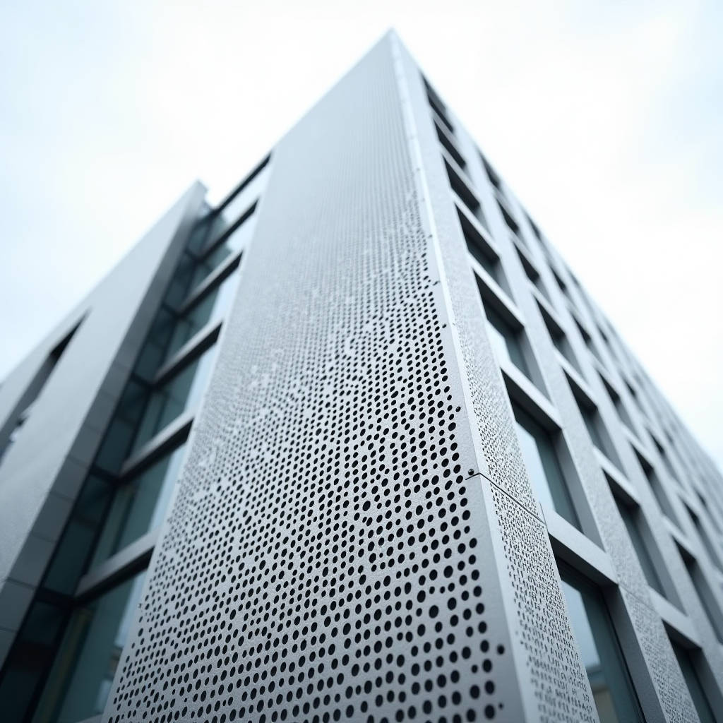
Designing a perforated metal building facade demands rigorous structural engineering beyond aesthetic pattern selection. The introduction of holes fundamentally alters the mechanical properties of solid aluminium cladding panels, reducing stiffness and changing how wind pressures distribute across the surface. Architects and contractors must account for these variables during the shop drawing phase to prevent excessive deflection or fastener failure. This technical overview addresses the critical relationship between open area percentage, alloy temper selection, and substructure spacing. Understanding these parameters ensures the perforated metal building facade meets international safety standards while maintaining long-term durability under dynamic environmental loads without compromising the intended visual transparency or ventilation performance required by modern architectural specifications.
The Structural Impact of Perforation on Solid Aluminium Panels
When specifying solid aluminium sheets for exterior cladding, the base material typically conforms to ASTM B209 standards for aluminum-alloy sheet and plate. Common alloys include 3003-H14 for general forming and 5005-H34 for anodized finishes. However, the punching process introduces stress concentrations around each hole perimeter. A standard 2.5mm thick panel with 40% open area effectively behaves structurally like a thinner solid sheet regarding bending resistance. Engineers cannot simply apply solid panel span tables to perforated variants.
The reduction in moment of inertia is non-linear. As the open area ratio increases, the effective cross-sectional area available to resist bending moments decreases proportionally, but the stress concentration factor at hole edges can amplify local stresses significantly. For high-wind regions, this necessitates either increasing the base thickness from 2.5mm to 3.0mm or reducing the support span. Testing per ASTM B209 confirms that H14 temper offers good formability but lower yield strength compared to H24 or H34 tempers. Selecting the correct temper becomes more critical when large perforations are involved, as the material must withstand both fabrication stresses and service loads without permanent deformation.
Calculating Effective Thickness and Deflection Limits
Deflection criteria for architectural metal facades typically limit movement to L/60 or 1 inch (25mm) under maximum design wind pressure, whichever is less. For perforated systems, calculating the effective moment of inertia (I_eff) requires adjustment factors based on hole geometry and stagger pattern. Staggered holes generally provide better structural continuity than straight-line patterns because they maintain diagonal ligaments that transfer shear forces more efficiently.
A practical engineering approach involves applying a reduction coefficient to the gross section properties. For circular holes in a staggered 60-degree pattern, the effective width for tension and bending calculations often approximates the net width minus one-third of the hole diameter, depending on pitch-to-diameter ratios. Conservative design practice suggests validating these theoretical reductions through physical load testing or finite element analysis (FEA) for complex geometries. Suppliers like Futeng® routinely provide project-specific structural data sheets that account for their specific tooling and punch characteristics, which vary between manufacturers due to differences in die clearance and burr management.
Wind Load Dynamics Specific to Perforated Surfaces
Wind interaction with a perforated metal building facade differs substantially from solid cladding. Airflow through the openings creates pressure equalization effects that can reduce net suction loads on the panel face, but this benefit is highly dependent on cavity depth and backing conditions. If the perforated screen acts as a rainscreen over a sealed air barrier, the pressure differential across the panel may be minimized. Conversely, if the perforated layer is the primary weather barrier, full wind loads must be resisted directly by the panel and its fixings.
ASCE 7-22 and Eurocode EN 1991-1-4 provide guidance for porous cladding, yet specific coefficients for architectural perforation patterns often require wind tunnel testing or computational fluid dynamics (CFD) modeling. The porosity ratio (open area divided by total area) determines whether the system qualifies as "open," "partially enclosed," or "solid" for code purposes. Generally, porosity below 10% is treated as solid; above 30%, significant pressure reduction factors may apply. Between these thresholds, conservative assumptions are prudent unless verified by project-specific aerodynamic studies.
Vortex Shedding and Aeroelastic Instability
Regular perforation patterns can induce vortex shedding at specific wind velocities, potentially causing resonant vibrations. This phenomenon occurs when the frequency of alternating vortices matches the natural frequency of the panel or substructure. While rare in heavy gauge aluminium, it has been documented in thin-gauge decorative screens with large unsupported spans. Mitigation strategies include varying hole sizes to break up coherent flow structures, adding stiffening ribs, or installing tuned mass dampers in extreme cases.
Damping characteristics of solid aluminium are relatively low compared to composite materials. Therefore, connection detailing plays a vital role in energy dissipation. Slotted holes at fixed points allow thermal expansion while providing friction damping. Isolator pads between panel and substructure further reduce vibration transmission. These details must be coordinated early in the design phase, as retrofitting damping solutions after installation is costly and visually intrusive.
Material Selection and Coating Durability Considerations
The increased surface area created by perforation exposes more raw edge to the environment. While aluminium naturally forms a protective oxide layer, cut edges remain vulnerable to galvanic corrosion if in contact with dissimilar metals or exposed to aggressive marine salts. Pre-finished coils offer superior edge protection compared to post-painted panels because the coil coating process applies primer and topcoat before slitting, though the sheared edge itself remains uncoated. For punched panels, the hole perimeter is always bare metal unless specifically treated post-fabrication.
PVDF (polyvinylidene fluoride) coatings meeting AAMA 2605 specifications provide excellent chalk and fade resistance for exterior applications. However, film thickness measurements on perforated panels can be misleading. Standard dry film thickness (DFT) gauges measure coating on flat surfaces; hole edges typically have thinner coverage due to paint flow during curing. Specifiers should request cross-section microscopy reports to verify edge coverage adequacy, particularly for coastal projects where salt spray penetration through perforations accelerates degradation.
| Parameter | 2.5mm Solid Panel | 2.5mm Perforated (40% Open) | 3.0mm Perforated (40% Open) |
|---|---|---|---|
| Effective Moment of Inertia (Relative) | 1.00x | 0.58x | 0.84x |
| Max Span @ 1.5kPa Suction (L/60) | 1200mm | 850mm | 1050mm |
| Weight (kg/m²) | 6.75 | 4.05 | 4.86 |
| Acoustic Transmission Loss (Approx.) | 28 dB | 12 dB | 14 dB |
| Fabrication Lead Time Factor | 1.0x | 1.3x | 1.4x |
Substructure Engineering and Connection Details
The supporting framework for a perforated metal building facade must accommodate reduced panel stiffness through closer purlin or rail spacing. Extruded aluminium T-profiles or omega channels are preferred over steel angles due to thermal compatibility and corrosion resistance. Fastener selection requires careful consideration of pull-out strength, which diminishes as hole proximity reduces effective engagement length. Stainless steel screws (A4-80 grade) with neoprene washers prevent water ingress and galvanic reaction with aluminium substrates.
Thermal expansion coefficients for aluminium (23.8 µm/m·K) necessitate slip joints at regular intervals. For perforated panels, differential expansion between the perforated skin and solid backing structure can cause buckling if restraints are too rigid. Design guidelines from the Aluminum Association recommend allowing 3-5mm movement capacity per panel module. Fixed points should be located near panel centers to distribute expansion symmetrically toward sliding ends. This arrangement prevents cumulative dimensional errors across long facade runs.
Detailing for Water Management and Ventilation
Perforated facades inherently compromise watertightness. Successful integration requires a secondary drainage plane behind the perforated layer. Flashings, gutters, and weep holes must be sized for increased water volume passing through the screen. Cavity ventilation rates depend directly on open area percentage; 20-30% openness typically provides adequate airflow for moisture drying without excessive rain penetration. Computational modeling helps optimize cavity depth and vent placement to balance drying potential with weather protection.
Edge terminations present unique challenges. Returning perforated panel edges creates clean sightlines but weakens the return leg due to interrupted material continuity. Reinforcing backer bars welded or riveted inside returns restore rigidity. Alternatively, solid border bands (unperforated margins) simplify fabrication and improve edge sealing. Minimum 25mm solid borders are recommended for reliable hemming and fastener concealment. These borders also serve as visual frames that enhance pattern legibility from distance.
Fabrication Constraints and Quality Control Protocols
CNC turret punching remains the dominant fabrication method for architectural perforation. Tool wear affects hole quality progressively; dull punches produce burrs and deformations that compromise coating adhesion and aesthetics. Reputable fabricators implement tool life monitoring programs and schedule preventive maintenance based on stroke counts rather than waiting for visible defects. Deburring operations are mandatory for exterior applications to eliminate sharp edges that accelerate coating breakdown and pose handling hazards.
Nesting optimization software minimizes material waste but must respect grain direction constraints. Rolling direction influences bend radius capability and anisotropic strength properties. Perforation patterns aligned parallel to rolling direction may exhibit different deflection characteristics than transverse orientations. Fabricators should document grain orientation on shop drawings and ensure consistency across matching panels. Batch traceability linking raw coil certificates to finished panel locations facilitates forensic investigation if field performance issues arise later.
Installation Sequencing and Field Verification
Site tolerances for perforated systems are tighter than solid cladding due to pattern alignment requirements across adjacent panels. Misaligned holes create visually distracting moiré effects even when individual panels meet dimensional specs. Survey control networks established before substructure installation enable real-time adjustment. Adjustable bracket systems with ±15mm range accommodate structural deviations without forcing panels out of plane.
Protective films applied during fabrication shield finishes during transit and installation but must be removed promptly after erection. UV-stabilized films resist degradation for extended outdoor exposure, yet prolonged adhesion can leave residue difficult to clean from textured perforated surfaces. Installation manuals should specify removal windows and approved cleaning agents compatible with PVDF coatings. Post-installation inspection protocols verify fastener torque, sealant continuity, and absence of transport damage before final handover.
Long-Term Performance Monitoring and Maintenance Access
Perforated facades accumulate debris differently than solid surfaces. Dust, pollen, and particulate matter lodge in hole edges, potentially staining surrounding areas during rainfall. Cleaning frequency depends on local pollution levels and rainfall patterns. Low-pressure washing with soft brushes avoids damaging hole edges or dislodging protective coatings. Abrasive methods are strictly prohibited as they remove mill finish and expose fresh aluminium to oxidation.
Access planning for maintenance must consider perforation fragility. Scaffold ties or swing stage anchors cannot attach directly to perforated panels without specialized spreader plates distributing point loads. Permanent access systems integrated into substructure design facilitate future inspections and cleaning. Documentation packages delivered at project completion should include as-built drawings identifying panel types, coating batch numbers, and recommended maintenance procedures tailored to the specific perforation geometry and environmental exposure category.
Engineering a perforated metal building facade successfully requires balancing architectural vision with mechanical reality. Every percentage increase in open area demands corresponding adjustments in thickness, span, or support density. Wind load behavior shifts from simple pressure resistance to complex aeroelastic interaction requiring specialized analysis. Material selection extends beyond alloy designation to encompass temper, coating edge coverage, and fabrication-induced property changes. Substructure design must reconcile thermal movement, vibration damping, and water management within constrained cavities. Only through systematic attention to these interconnected variables can designers achieve durable, code-compliant perforated envelopes that perform reliably throughout their service life while delivering intended aesthetic and environmental benefits.