Structural Integrity and Wind Load Management for Perforated GRC Panels
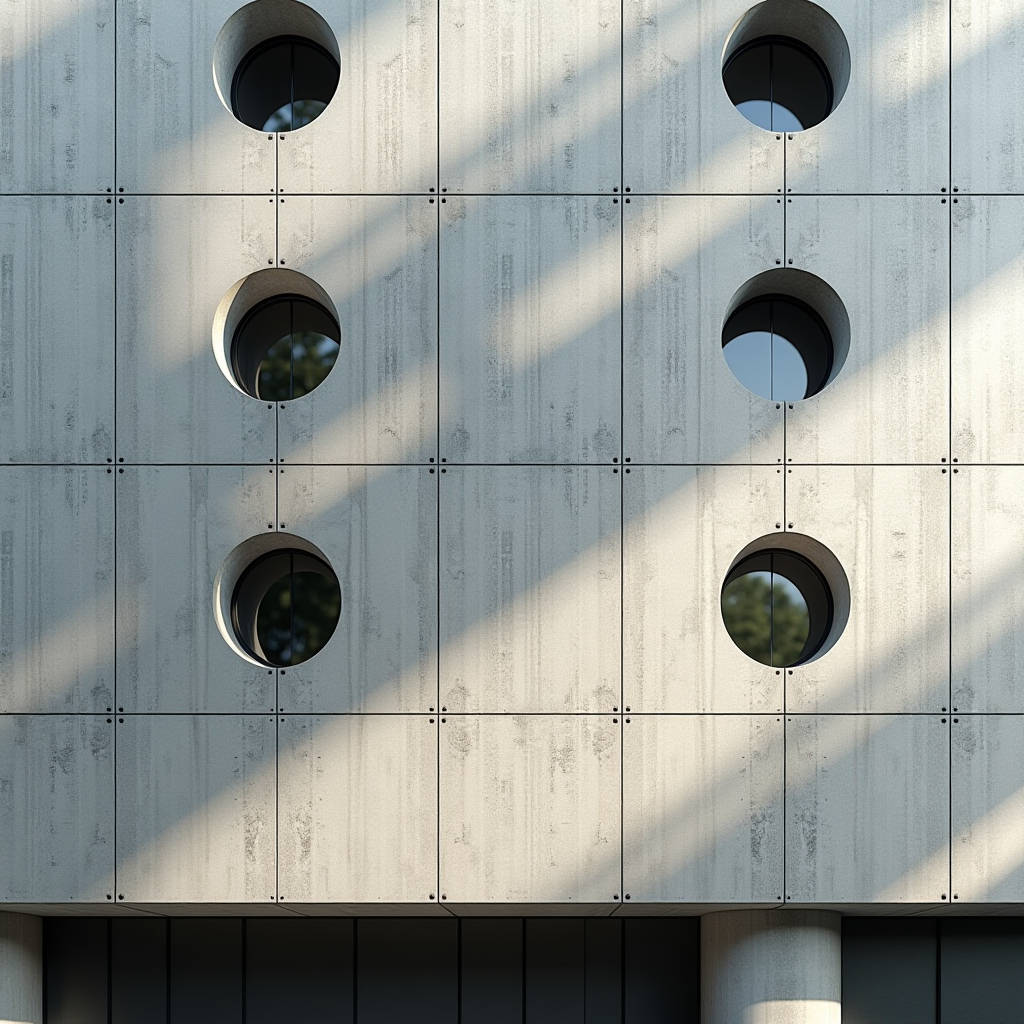
Integrating perforated grc panels into modern architectural facades introduces complex structural challenges that extend far beyond aesthetic pattern selection. While the visual permeability of these elements creates dynamic light play and ventilation, the reduction in material mass significantly alters the panel's moment of inertia and load-bearing capacity. Engineers and procurement managers must recognize that introducing voids into Glass Fiber Reinforced Concrete transforms a monolithic shell into a discontinuous structural member requiring specialized steel armatures and rigorous wind tunnel validation. Failure to account for stress concentrations around perforation boundaries often leads to premature cracking or anchor fatigue. Successful project delivery depends on treating these components as engineered composite systems rather than standard decorative cladding, necessitating close coordination between fabricators and structural consultants to validate safety factors against local building codes.
Structural Implications of Material Reduction
The fundamental engineering constraint when specifying perforated grc panels is the direct correlation between open area percentage and residual flexural strength. Standard solid GRC skins typically range from 13mm to 20mm in thickness, relying on the continuous cementitious matrix to distribute loads across embedded alkali-resistant glass fibers. When perforations are introduced, this load path is interrupted. A panel with 40% open area does not retain 60% of its original strength; due to stress risers at the edges of each hole, the effective structural capacity can drop disproportionately unless compensated by localized thickening or additional ribbing.
Stress concentration factors (SCF) around circular holes in brittle composite materials can reach values of 3.0 or higher depending on the hole-to-panel width ratio. For rectangular or slot-shaped perforations, which are common in contemporary facade designs, sharp corners act as crack initiation points under cyclic wind loading. Industry best practice mandates radiusing all internal corners to a minimum of 5mm to mitigate this risk. Furthermore, the proximity of perforations to panel edges and fixing points requires strict adherence to minimum margin distances. The International Glassfibre Reinforced Concrete Association (GRCA) provides specific guidance on edge distances relative to hole diameter, which must be verified during the shop drawing approval phase to prevent blowout failures during installation or service.
Fiber Orientation and Matrix Continuity
In spray-suction manufacturing processes, the random orientation of chopped strands generally provides isotropic properties in solid sections. However, in highly perforated zones, the continuity of the fiber network is physically severed. Manufacturers utilizing hand-layup or filament winding techniques for complex perforated geometries can strategically align continuous rovings around opening perimeters to restore tensile capacity. This directional reinforcement is critical for large-format panels where the span between supports exceeds standard limits. Procurement specifications should explicitly require documentation of reinforcement detailing for any perforated zone exceeding 300mm in dimension, ensuring that the loss of matrix integrity is counteracted by mechanical means rather than relying solely on the base mix design.
Wind Load Dynamics and Pressure Equalization
Ventilated facades incorporating perforated grc panels operate differently than sealed barrier walls regarding wind pressure distribution. The porosity of the screen layer allows partial pressure equalization between the exterior environment and the cavity behind the cladding. According to ASCE 7-22 standards for minimum design loads, the net wind pressure on a porous screen is a function of the solidity ratio (the ratio of solid area to gross area). For panels with high perforation density, the external positive pressure is partially transmitted through the openings, reducing the net differential load on the panel itself but increasing the demand on the substructure and air barrier system.
Conversely, suction forces on the leeward side of a building can create significant uplift on perforated elements. If the cavity behind the panel is not properly compartmentalized with air dams, wind can enter through perforations on the windward side and pressurize the cavity, creating outward force on leeward panels that they may not have been designed to resist. Engineering calculations must therefore consider both the direct wind load on the perforated face and the potential cavity pressure effects. Computational Fluid Dynamics (CFD) modeling is increasingly used for projects with complex geometries or irregular perforation patterns to predict localized pressure coefficients that standard code provisions may not adequately capture.
| Solidity Ratio (φ) | Net Pressure Coefficient (Cn) | Cavity Ventilation Requirement | Recommended Structural Verification |
|---|---|---|---|
| > 0.8 | 1.0 - 1.2 | Minimal; treat as near-solid | Standard flexural testing per ASTM C947 |
| 0.5 - 0.8 | 0.7 - 0.9 | Moderate; compartmentalize every 2 floors | Finite Element Analysis (FEA) for stress concentrations |
| 0.3 - 0.5 | 0.4 - 0.6 | High; full pressure equalization design | Prototype wind tunnel testing recommended |
| < 0.3 | 0.2 - 0.4 | Maximum; verify air barrier independence | Specialized structural assessment; check vibration modes |
Aeroelastic Instability and Vibration
Slender, highly perforated GRC elements are susceptible to wind-induced vibration, particularly vortex shedding and galloping instabilities. Unlike solid panels that dampen aerodynamic energy through mass, lightweight perforated screens can resonate if their natural frequency aligns with prevailing wind frequencies. This phenomenon is most critical in tall buildings or exposed coastal environments. Damping measures, such as tuned mass dampers integrated into the support frame or increased connection stiffness, may be required. Suppliers like Futeng® often recommend conducting dynamic response analyses for perforated panels exceeding 2 meters in unsupported span to ensure serviceability limits are met and occupant comfort is maintained, preventing perceptible movement or audible rattling during storm events.
Steel Armature Design for Discontinuous Sections
The internal steel framework within perforated grc panels serves as the primary load-transfer mechanism, bridging gaps created by voids and anchoring the fragile cementitious skin to the building structure. In solid panels, a simple ladder or truss frame suffices. In perforated variants, the armature must be custom-fabricated to follow the solid ligaments between holes. This often results in complex, non-standard steel assemblies that require precise jigging during fabrication to maintain dimensional tolerance.
Corrosion protection of this embedded steel is paramount, as the reduced concrete cover around perforation edges increases vulnerability to moisture ingress. Galvanizing alone may be insufficient for aggressive marine or industrial environments. Epoxy coating or stainless steel reinforcement should be specified for critical load paths. The bond between the steel and the GRC matrix relies on mechanical interlock and chemical adhesion; in narrow ligaments between closely spaced holes, achieving adequate embedment length becomes challenging. Designers must verify that development lengths comply with ACI 548 guidelines for thin-section composites, potentially requiring welded studs or expanded metal lath to enhance shear transfer in constrained zones.
Connection Detailing and Differential Movement
Anchorage systems for perforated grc panels must accommodate thermal expansion, creep, and seismic drift without inducing point loads that could fracture the weakened sections. Slotted connections with neoprene pads are standard, but the placement of anchors relative to perforations requires careful coordination. Anchors should never be located within one hole-diameter of a perforation edge. Instead, they must be positioned in solid zones with sufficient volume to develop pull-out resistance. For large panels, multiple pick-up points distribute gravity loads more evenly, reducing bending moments in the panel plane. Adjustable brackets allow for field tolerances, accommodating deviations in the primary structure without forcing the GRC panel out of alignment, which could induce locked-in stresses that manifest as delayed cracking.
Manufacturing Tolerances and Quality Assurance
The production of perforated grc panels introduces variables that do not exist in solid panel manufacturing. Creating voids requires either removable formwork inserts or post-casting CNC machining. Each method carries distinct risks. Molded perforations yield smoother edges and better fiber continuity but increase mold complexity and cost. Machined perforations offer greater design flexibility but cut through cured fibers, exposing raw ends to environmental attack and reducing local strength. Regardless of method, dimensional tolerances for hole position and size are typically ±3mm per GRCA standards, but tighter controls may be necessary for modular facade systems where misalignment accumulates over multiple bays.
Quality assurance protocols must include non-destructive testing (NDT) to verify steel placement and detect hidden voids or delamination near perforation edges. Ultrasonic pulse velocity testing or ground-penetrating radar can map internal conditions without damaging the finish. Visual inspection alone is insufficient for structural validation. Additionally, sample panels should be subjected to destructive testing to confirm ultimate load capacity matches theoretical predictions, especially for novel perforation patterns lacking historical performance data. This empirical verification bridges the gap between analytical models and real-world material behavior, providing confidence to engineers and insurers.
Surface Treatment and Durability Considerations
The increased surface area created by perforation edges exposes more material to weathering agents. Unsealed cut edges absorb water rapidly, leading to freeze-thaw damage or efflorescence staining. Factory-applied sealants or integral hydrophobic admixtures are essential for long-term durability. Acid etching or sandblasting after perforation can remove weak surface laitance and expose aggregate, improving both aesthetics and weather resistance. However, aggressive finishing can also reduce effective section thickness. Specifications should define acceptable post-processing methods and maximum material removal limits. Color consistency across perforated faces can vary due to differential curing rates around voids; mock-ups should establish acceptance criteria for tonal variation before full-scale production commences.
Installation Logistics and Site Handling
Perforated grc panels are inherently more fragile during handling than their solid counterparts. Lifting points must be engineered specifically for the perforated configuration, avoiding stress concentrations near voids. Spreader beams and vacuum lifters with customized pad layouts distribute suction forces across solid zones only. On-site storage requires flat, level support to prevent warping; stacking perforated panels directly on top of each other without protective interleaving can cause edge damage or breakage. Installation sequences should minimize temporary propping, as uneven support can induce cracking in weakened sections.
Coordination with adjacent trades is critical. Penetrations for lighting, signage, or HVAC louvers that intersect perforated zones must be pre-planned and reinforced during fabrication. Field modifications to perforated panels are strongly discouraged and often void manufacturer warranties due to the risk of compromising structural integrity. Detailed installation manuals should specify torque limits for fasteners, sequence of tightening, and procedures for adjusting misaligned panels without prying against fragile edges. Training installers on the unique handling requirements of perforated GRC prevents costly replacements and schedule delays caused by site damage.
Regulatory Compliance and Testing Standards
Navigating building code approvals for perforated grc panels requires demonstrating equivalence to prescriptive requirements for solid cladding. Since most codes lack specific provisions for perforated cementitious composites, performance-based design paths are typically employed. This involves submitting comprehensive test reports validating fire resistance, structural adequacy, and weather tightness. Fire testing per ASTM E119 or EN 13501 must account for the chimney effect created by vertical perforation arrays, which can accelerate flame spread through the facade assembly. Intumescent coatings or fire-stopping barriers within the cavity may be required to maintain compartmentation.
Water penetration testing per ASTM E331 or CWCT standards should simulate wind-driven rain entering through perforations to verify that the secondary drainage plane functions correctly. Air leakage testing confirms that unintended infiltration through the perforated screen does not compromise building envelope performance. Documentation packages submitted to authorities having jurisdiction (AHJs) should include third-party certification from accredited laboratories, structural calculation reports stamped by licensed engineers, and maintenance manuals outlining inspection intervals for perforation edges and connections. Proactive engagement with AHJs during design development streamlines approval processes and avoids costly redesigns late in the project timeline.
Long-Term Maintenance and Inspection Protocols
The lifecycle performance of perforated grc panels depends on proactive maintenance regimes tailored to their unique vulnerability profiles. Annual visual inspections should focus on crack propagation around perforation edges, corrosion staining from embedded steel, and sealant degradation at joints and hole margins. Access equipment planning must consider that cleaning perforated facades requires reaching both outer and inner surfaces to prevent pollutant accumulation within voids. Pressure washing parameters must be restricted to avoid eroding the cementitious matrix at exposed edges.
Repair protocols for damaged perforations differ from solid panel repairs. Patching compounds must match the original mix design and include compatible fiber reinforcement to restore structural continuity. Cosmetic fills alone are insufficient for load-bearing zones. Major damage may require panel replacement rather than repair, emphasizing the importance of maintaining spare inventory and accurate as-built records. Lifecycle cost analyses should factor in these specialized maintenance needs when comparing perforated GRC to alternative materials, ensuring that initial aesthetic benefits do not translate into unsustainable operational burdens over the building's service life.