Perforated Aluminum Strip Fabrication Tolerances For Solid Cladding Systems
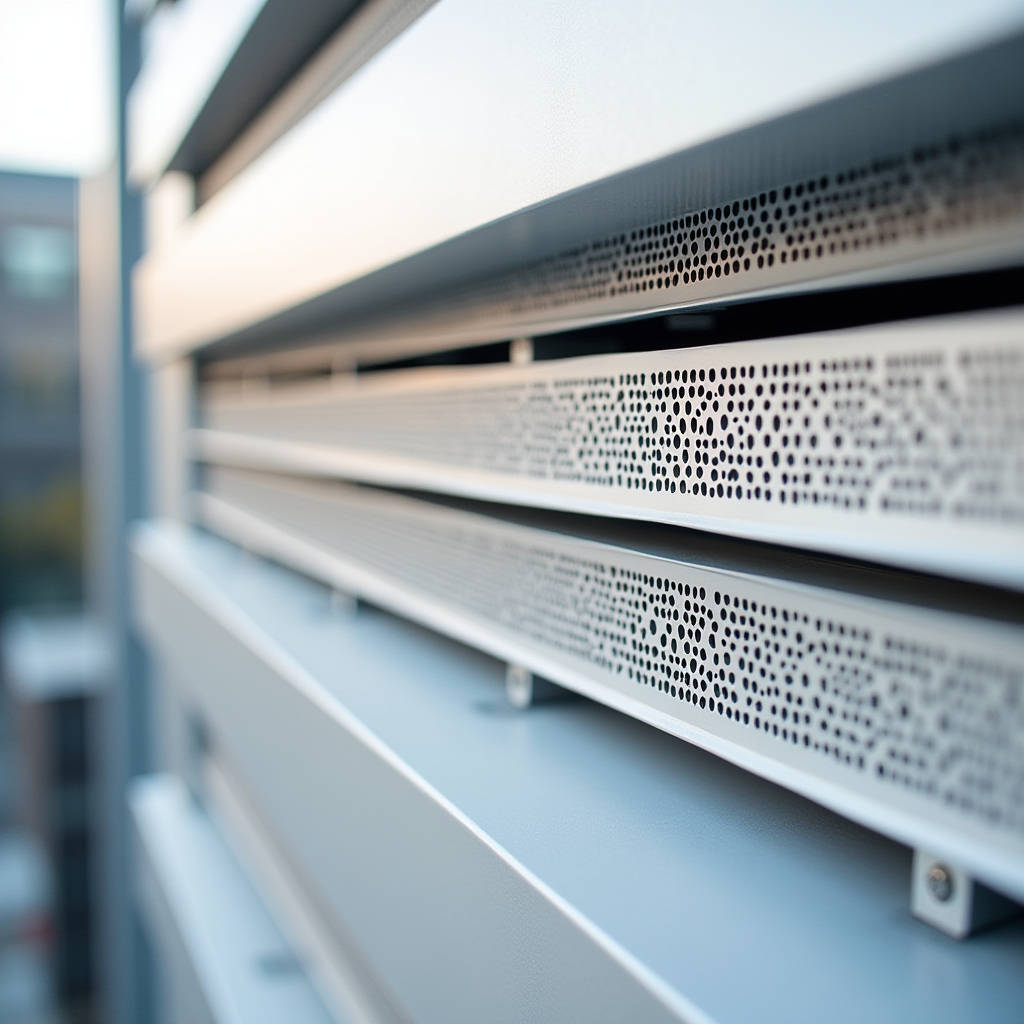
Integrating a perforated aluminum strip into solid aluminium cladding panels demands strict adherence to fabrication tolerances that differ significantly from standard sheet metal work. When processing 2.0mm to 3.0mm solid aluminum for architectural facades, the punching operation introduces internal stresses that can compromise panel flatness if not properly managed. This component serves critical functions in ventilation, acoustic modulation, and aesthetic screening within curtain wall systems, yet its structural performance relies entirely on maintaining dimensional stability during manufacturing. Understanding the relationship between open area ratios, alloy temper selection, and post-punching leveling is essential for contractors and architects specifying these elements. The following technical analysis addresses the specific engineering constraints required to produce high-performance perforated aluminum strip details that meet rigorous facade standards without sacrificing coating integrity or long-term durability in exterior environments.
Material Selection and Alloy Temper Constraints
The foundation of any reliable perforated aluminum strip application lies in selecting the correct base material specification. While generic suppliers may offer various alloys, architectural solid aluminium cladding panels strictly require AA5005-H14 or AA5754-H22 tempers when perforation is involved. These alloys provide the optimal balance between formability and tensile strength necessary to withstand the shearing forces of CNC punching without excessive edge burring or subsequent warping. Using softer tempers like H111 often results in elongated holes and loss of geometric precision, while harder tempers like H18 are prone to cracking along the perforation perimeter.
Compliance with ASTM B209 / B209M standards is non-negotiable for thickness tolerance verification. A nominal 3.0mm solid aluminum sheet must maintain a tolerance of ±0.15mm across the entire width before perforation begins. Deviations beyond this limit cause inconsistent punch penetration depths, leading to variable hole geometry and compromised structural rigidity in the final perforated aluminum strip assembly. Procurement teams should always request mill test certificates confirming both chemical composition and mechanical properties specifically for the batch being processed, as recycled content variations can subtly alter punching behavior.
Tensile Strength Considerations for Narrow Strips
When fabricating narrow perforated aluminum strip components less than 150mm wide, the reduction in cross-sectional area due to perforations significantly affects load-bearing capacity. Engineers must calculate the net section modulus based on the actual open area percentage rather than gross dimensions. For example, a 3.0mm thick strip with 40% open area effectively behaves as a 1.8mm solid section regarding bending resistance. This derating factor must be incorporated into wind load calculations and bracket spacing determinations to prevent permanent deformation under service loads.
- AA5005-H14: Recommended for decorative strips with open areas up to 50%, offering excellent anodizing and PVDF coating compatibility
- AA5754-H22: Preferred for structural ventilation strips requiring higher yield strength, particularly in coastal or high-wind zones
- AA3003-H14: Acceptable only for interior applications or non-structural trim where corrosion resistance requirements are reduced
- AA6061-T6: Generally avoided for perforated cladding due to poor formability and susceptibility to stress corrosion cracking at hole edges
CNC Punching Parameters and Flatness Control
Achieving acceptable flatness in perforated aluminum strip production requires meticulous control of CNC punching parameters. The shearing action during perforation induces compressive stresses around each hole and tensile stresses in the ligaments between holes. Without proper management, these residual stresses manifest as longitudinal bowing or lateral twisting that cannot be corrected through simple mechanical leveling. Professional fabricators employ progressive punching sequences that distribute stress symmetrically across the sheet width, alternating punch patterns to balance internal forces rather than completing one section before moving to the next.
Tool clearance settings directly impact edge quality and subsequent coating performance. For 3.0mm solid aluminum, punch-to-die clearance should be maintained at 8-10% of material thickness (0.24-0.30mm). Excessive clearance produces rollover and burrs that trap moisture and accelerate coating failure, while insufficient clearance increases tool wear and generates heat that locally anneals the aluminum, creating soft spots vulnerable to denting. Regular tool maintenance schedules must account for the abrasive nature of aluminum oxide formation on punch surfaces.
Post-Punching Leveling Protocols
Even with optimized punching parameters, some degree of stress-induced distortion is inevitable in perforated aluminum strip manufacturing. Multi-roll leveling machines with adjustable backup roll configurations are essential for restoring flatness to within acceptable architectural tolerances. The leveling process must be calibrated specifically for perforated material, as the reduced stiffness requires different pressure profiles than solid sheet. Over-leveling can stretch the ligaments and permanently enlarge hole dimensions, while under-leveling leaves residual waviness visible after installation.
Industry best practice mandates verifying flatness against a precision ground table using feeler gauges at multiple points along the strip length. According to AAMA 605 guidelines for high-performance organic coatings, substrate flatness deviations exceeding 1.5mm per meter typically result in visible surface imperfections after PVDF application. Contractors should establish incoming inspection protocols that reject perforated aluminum strip components failing to meet project-specific flatness criteria before they enter the coating line, as rework after finishing is rarely successful.
PVDF Coating Adhesion on Perforated Surfaces
The perforation process creates thousands of fresh aluminum edges that present unique challenges for PVDF fluoropolymer coating systems. These cut edges have different electrochemical characteristics than the mill-finished surface, potentially leading to differential curing rates and adhesion failures if pretreatment chemistry is not adjusted accordingly. Standard chromate or zirconium-based conversion coatings must achieve complete coverage inside hole walls and along shear-affected zones to provide adequate corrosion protection and paint bonding.
Coating thickness measurements on perforated aluminum strip require specialized techniques due to the discontinuous surface. Traditional magnetic or eddy-current gauges cannot reliably measure film build on narrow ligaments or near hole edges. Destructive cross-section analysis remains the most accurate verification method for critical projects, supplemented by non-destructive testing on adjacent solid areas. Minimum dry film thickness of 25μm primer plus 25μm PVDF topcoat must be maintained on all accessible surfaces, with particular attention to ensuring complete coverage of downward-facing hole edges where liquid paint tends to drain away during application.
| Performance Parameter | Standard PVDF System | Enhanced Edge Protection System | Testing Reference |
|---|---|---|---|
| Salt Spray Resistance (Hours) | 1,000 - 1,500 | 2,000 - 3,000 | ASTM B117 |
| Humidity Resistance (Hours) | 1,000 | 2,000+ | ASTM D2247 |
| Cross-Cut Adhesion (Tape Test) | 4B - 5B | 5B Consistent | ASTM D3359 |
| Edge Creep Resistance (mm) | ≤ 3.0 | ≤ 1.5 | ISO 9227 |
| Color Retention (ΔE after 10 yrs) | ≤ 5.0 Hunter Units | ≤ 3.0 Hunter Units | AAMA 2605 |
For projects in aggressive marine or industrial environments, specifying enhanced edge protection systems provides measurable longevity benefits. These systems incorporate additional barrier coats or modified resin formulations designed to bridge micro-gaps at perforation boundaries. Suppliers like Futeng® have developed proprietary pretreatment protocols specifically addressing the unique surface chemistry of perforated aluminum strip components, demonstrating improved salt spray performance in comparative testing. Such technical refinements distinguish architectural-grade products from commodity perforated metal intended for industrial filtration or screening applications.
Structural Integration and Installation Tolerances
Designing attachment systems for perforated aluminum strip elements requires accounting for thermal expansion coefficients and reduced stiffness compared to solid cladding. Aluminum expands approximately 23.4 μm/m·°C, meaning a 3-meter strip experiences nearly 4mm of length change across a 60°C seasonal temperature range. Fixing points must accommodate this movement through slotted holes or floating clip arrangements to prevent buckling or fastener fatigue. Rigidly fixing both ends of a perforated aluminum strip without provision for thermal movement guarantees premature system failure.
Bracket spacing calculations must incorporate the effective moment of inertia of the perforated section, which decreases non-linearly with increasing open area. Finite element modeling or physical load testing according to ISO 16932 principles provides more reliable design data than simplified beam equations, especially for complex perforation patterns with irregular ligament geometries. Safety factors for perforated aluminum strip connections should be increased by 20-30% above standard solid panel values to account for stress concentrations at hole perimeters and potential fabrication variability.
Sequencing and On-Site Handling Protocols
Installation sequencing significantly impacts the final appearance and performance of perforated aluminum strip assemblies. These components should be installed last in the cladding sequence whenever possible to minimize exposure to construction debris, welding sparks, and sealant overspray that can permanently damage PVDF finishes. Protective films must remain in place until final handover, but installers should verify that adhesive residues will not degrade upon UV exposure during extended outdoor storage. Temperature-sensitive adhesives used on perforated surfaces sometimes fail to release cleanly after months of weathering, leaving ghost marks that resist conventional cleaning methods.
On-site cutting or drilling of pre-finished perforated aluminum strip should be prohibited except for emergency field modifications. Any unavoidable site work requires immediate touch-up treatment with manufacturer-approved repair compounds matched to the original coating system. Unsealed cut edges expose bare aluminum to atmospheric corrosion that rapidly undermines adjacent factory-applied finishes, creating unsightly staining and potential warranty exclusions. Project specifications should clearly delineate responsibility for field damage remediation and establish acceptance criteria for repaired areas based on viewing distance and lighting conditions.
Quality Verification and Documentation Requirements
Comprehensive quality documentation for perforated aluminum strip components extends beyond standard material certificates to include process-specific verification records. Fabricators should provide punch tooling inspection logs confirming dimensional accuracy throughout production runs, leveling machine calibration certificates, and coating thickness maps showing measurements taken at representative locations including hole edges and strip centers. Batch samples retained from each production lot enable future forensic analysis if field performance issues arise years after installation.
Third-party testing laboratories accredited to ISO/IEC 17025 standards should perform independent validation of critical performance parameters for large-scale projects. Testing scope typically includes accelerated weathering, adhesion verification after humidity cycling, and mechanical property confirmation of perforated specimens representing actual as-built conditions. This investment in independent verification provides defensible evidence of compliance when disputes arise and establishes baseline expectations for long-term facade maintenance planning.
Successful integration of perforated aluminum strip details into solid aluminium cladding systems ultimately depends on treating these components as engineered building products rather than generic metal supplies. Each stage from alloy selection through final installation introduces variables that compound multiplicatively if not actively managed. Architects and contractors who invest time in understanding these technical nuances consistently achieve superior outcomes compared to those relying solely on supplier assurances. The margin between acceptable performance and premature failure in perforated facade elements is often measured in tenths of millimeters and microns of coating thickness, demanding precision that only disciplined manufacturing processes can deliver reliably across entire project volumes.