Perforated Aluminum Mesh Facade Engineering Open Area and Wind Load Safety
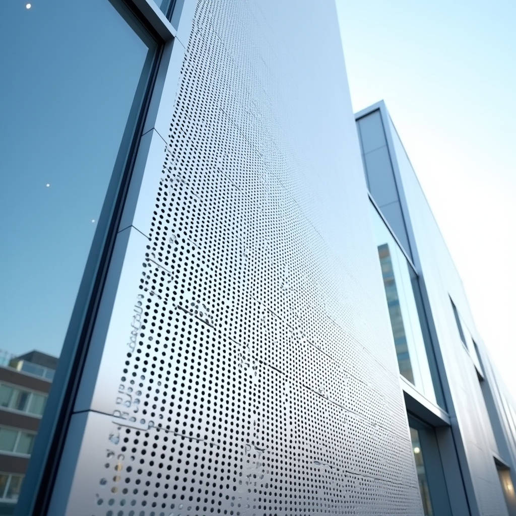
Integrating perforated aluminum mesh into commercial building envelopes demands rigorous engineering beyond aesthetic selection. Architects and contractors frequently underestimate how hole patterns alter structural behavior under wind pressure. Unlike solid cladding, perforated aluminum mesh acts as a semi-permeable barrier where open area percentage directly dictates both ventilation performance and wind load transfer to the substructure. Miscalculating this ratio leads to panel deformation, fastener failure, or inadequate airflow. This technical analysis addresses the critical relationship between perforation geometry, alloy temper selection, and anchoring systems in solid aluminum sheets. We examine specific engineering parameters required to ensure long-term facade stability, focusing on 2.0mm to 3.0mm solid aluminum substrates that meet international construction standards rather than lightweight composite alternatives.
Open Area Percentage and Structural Implications
The open area percentage is the single most critical variable when specifying perforated aluminum mesh for exterior facades. This metric represents the ratio of void space to total surface area and fundamentally changes how the panel interacts with environmental forces. For solid aluminum cladding panels ranging from 2.0mm to 3.0mm thickness, maintaining structural rigidity becomes increasingly challenging as open area exceeds 40%. When designers request high transparency for visual permeability, the remaining solid material must carry significantly higher stress concentrations around each perforation point.
Engineering calculations must account for the reduced moment of inertia in perforated sections. A standard 3.0mm AA5754-H14 aluminum sheet has a baseline yield strength of approximately 160 MPa according to ASTM B209 specifications. However, introducing a 50% open area pattern effectively halves the cross-sectional area available to resist bending moments. This reduction necessitates closer support spacing or thicker base material to maintain equivalent deflection limits. Most facade engineers target a maximum deflection of L/180 under service loads, but perforated panels often require stricter L/240 criteria due to visible distortion risks across large transparent surfaces.
Hole geometry also influences stress distribution patterns. Round holes arranged in staggered 60-degree patterns provide more uniform load paths compared to square or slot perforations aligned with panel edges. Staggered round holes distribute tensile stresses circumferentially, reducing peak concentration factors at corners where cracks typically initiate. Square holes create stress risers at sharp corners that can propagate fatigue failures under cyclic wind loading. Slot perforations oriented parallel to the primary span direction offer minimal resistance to bending and should generally be avoided in high-wind zones unless reinforced with back stiffeners.
Calculating Effective Wind Loads on Permeable Surfaces
Wind load assessment for perforated aluminum mesh differs substantially from solid wall cladding. Airflow through perforations reduces overall drag coefficients but introduces complex turbulence effects that local codes may not fully address. The ASCE 7-22 standard provides guidance for porous signs and fences, yet architectural facades present unique boundary conditions requiring project-specific wind tunnel testing or computational fluid dynamics modeling for buildings exceeding 60 meters in height.
A practical engineering approach involves applying a porosity correction factor to standard pressure coefficients. For perforated aluminum mesh with 30-50% open area, net wind pressures typically reduce by 15-25% compared to solid surfaces. However, this reduction is non-linear and varies with wind angle of attack. Oblique winds can actually increase localized suction near panel edges where flow separation occurs. Engineers must verify edge zone fixings against unreduced design pressures regardless of central field porosity benefits. Corner regions and parapet caps experience amplified vortices that demand conservative fastener spacing independent of open area calculations.
Gust response factors also require adjustment for permeable assemblies. Solid panels respond quasi-statically to wind gusts due to their mass and damping characteristics. Perforated panels exhibit different dynamic behavior because airflow through holes creates additional aerodynamic damping while simultaneously reducing effective mass. This dual effect can either mitigate or amplify resonant responses depending on natural frequency alignment with dominant wind energy spectra. Project-specific dynamic analysis becomes mandatory for large-format perforated screens exceeding 4 meters in unsupported span.
Material Specifications for Exterior Durability
Selecting appropriate aluminum alloy and temper ensures perforated aluminum mesh maintains dimensional stability throughout decades of thermal cycling and moisture exposure. Marine-grade alloys dominate exterior applications due to superior corrosion resistance in coastal and industrial environments. AA5754-H14 and AA5052-H32 represent industry benchmarks for perforated facade panels, offering balanced formability during fabrication and adequate strength after installation. These manganese-magnesium alloys develop protective oxide layers that self-heal when scratched, unlike heat-treated 6xxx series alloys prone to intergranular corrosion in humid climates.
Temper designation critically affects post-perforation flatness. H14 strain-hardened tempers retain better shape memory after punching operations compared to softer H12 or O-tempers. The cold-working process during perforation induces residual stresses that can cause warping if base material lacks sufficient hardness. Suppliers like Futeng® typically recommend H14 or H24 tempers for panels exceeding 1.5 meters in width to minimize oil-canning effects visible under raking sunlight. Thicker 3.0mm gauges tolerate wider hole margins without distortion, whereas 2.0mm sheets require tighter quality control during coil feeding and punch clearance adjustments.
Surface treatment specifications must align with expected service life and environmental severity. Powder coating alone rarely suffices for architectural perforated aluminum mesh exposed to UV radiation and salt spray. Polyvinylidene fluoride (PVDF) resin systems meeting AAMA 2605-21 performance requirements provide minimum 20-year color retention and chalk resistance. Film thickness measurements should verify 25-30 microns dry film thickness applied over chromate-free pretreatment. Thinner coatings risk premature fading on sun-exposed elevations, while excessive buildup can bridge small perforations and alter intended open area ratios. Quality assurance protocols must include adhesion cross-hatch testing and MEK rub resistance verification before shipment.
| Parameter | AA5754-H14 (2.5mm) | AA5052-H32 (2.0mm) | AA6061-T6 (3.0mm) |
|---|---|---|---|
| Yield Strength (MPa) | 160 | 190 | 240 |
| Elongation (%) | 8 | 7 | 10 |
| Marine Corrosion Resistance | Excellent | Excellent | Moderate |
| Post-Perforation Flatness | High | Medium | Low |
| Recommended Max Open Area | 50% | 40% | 55% |
| PVDF Coating Adhesion | Class 0 | Class 0 | Class 1 |
Thermal Expansion Management in Perforated Assemblies
Aluminum expands approximately 23.4 µm/m·°C according to ISO 16938-1 thermal property standards. A 3-meter perforated panel experiences 2.1mm length change across a 30°C seasonal temperature swing. Perforations complicate expansion accommodation because hole patterns create anisotropic stiffness that constrains uniform movement. Panels with directional slot perforations expand differently along major versus minor axes, potentially inducing shear stresses at fixed connection points.
Slotted mounting holes provide essential compliance in perimeter fixings. Standard practice specifies 8mm diameter slots oriented parallel to expected expansion direction, allowing ±3mm movement capacity. Fixed anchor points should locate near panel centers to establish stable reference positions while permitting bidirectional growth toward edges. Rigid four-corner bolting without slip planes guarantees eventual fastener shear or panel buckling. Silicone sealants at panel joints must accommodate calculated movement ranges plus 25% safety margin without losing adhesion or cohesion.
Shadow line reveals between adjacent perforated panels serve dual purposes: accommodating differential expansion and masking alignment tolerances. Minimum 15mm reveal widths allow visual forgiveness of ±2mm installation variance while providing adequate sealant depth-to-width ratios. Narrower joints risk compression failure during hot weather expansion phases. Backer rod sizing must match joint width precisely to prevent three-sided adhesion that causes cohesive tearing under cyclic movement.
Fabrication Tolerances and Installation Protocols
Precision during perforation manufacturing determines final facade appearance and structural reliability. Hole diameter tolerances typically hold ±0.1mm for CNC turret punching, but cumulative pitch errors across wide sheets can exceed acceptable limits. Industry standards permit ±1.5mm deviation over 2-meter spans for architectural grade perforated aluminum mesh. Exceeding this tolerance creates misalignment issues when multiple panels join at continuous horizontal bands. Fabricators must implement statistical process control monitoring punch wear and strip feed accuracy throughout production runs.
Deburring quality directly impacts coating performance and safety. Sharp edges left after punching concentrate electric fields during electrostatic powder application, causing thin spots vulnerable to corrosion initiation. Proper deburring removes burrs entirely while creating slight radii that promote even coating coverage. Manual inspection remains necessary despite automated brushing equipment because hole geometries vary accessibility. Safety considerations also mandate smooth edges for installers handling panels without gloves during positioning adjustments.
Substructure alignment prerequisites exceed those for solid cladding due to perforated panels revealing background elements. Any substrate irregularity shows through transparent areas, making shimming and leveling critically important. Laser scanning existing structures identifies deviations before panel fabrication begins. Adjustable bracket systems with ±20mm travel range accommodate as-built conditions without custom panel modifications. Rigid welded connections lack field adjustability and frequently cause schedule delays when site conditions differ from design assumptions.
Ventilation Performance Validation Methods
Beyond structural concerns, perforated aluminum mesh often serves functional ventilation roles in parking garages, mechanical screens, and passive cooling facades. Actual airflow rates depend on discharge coefficients that deviate significantly from theoretical open area percentages due to friction losses and turbulence at hole entrances. Empirical testing per ASHRAE Handbook methodologies establishes real-world performance curves relating pressure differential to volumetric flow rate.
Computational models calibrated against physical test data predict system-level ventilation effectiveness. Boundary layer development across perforated surfaces reduces effective porosity near panel frames and adjacent solid walls. Edge effects can decrease overall airflow by 10-15% compared to infinite array assumptions. Designers must specify oversize open areas or additional panel quantity to compensate for these losses when meeting code-mandated air exchange rates. Post-installation anemometer surveys validate achieved performance and identify blockage issues from debris accumulation or incorrect panel orientation.
Maintenance access provisions integrate with ventilation function requirements. Removable perforated panels facilitate filter replacement and equipment servicing behind screens. Quick-release latching mechanisms enable tool-free removal while maintaining security against unauthorized access. Panel weight limitations govern maximum removable size; single-person handling typically caps at 25kg requiring segmentation of larger ventilation zones. Color-coded identification systems prevent reinstallation errors that could reverse intended airflow directions or compromise weather sealing integrity.
Successful perforated aluminum mesh facade projects balance competing demands of transparency, strength, durability, and cost. Early collaboration between architects, engineers, and fabricators prevents costly redesigns caused by overlooked technical constraints. Verifying open area calculations against structural capacity, selecting marine-grade alloys with proven PVDF coatings, and detailing expansion-compatible fixings establish foundations for long-term performance. Rigorous fabrication quality control and methodical installation protocols translate design intent into built reality without compromising safety or aesthetics. Continuous industry research refines understanding of permeable facade behavior, supporting increasingly ambitious architectural expressions grounded in sound engineering principles.