Perforated Aluminum Channel Integration in Solid Cladding Support Systems
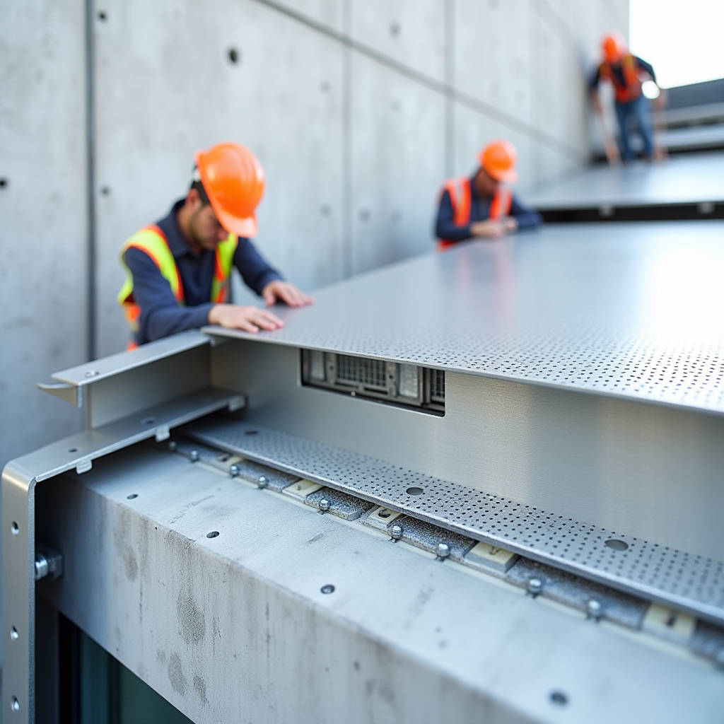
Integrating a perforated aluminum channel into facade substructures requires precise engineering to ensure compatibility with solid aluminium cladding panels. Unlike generic industrial strut systems, architectural channels must accommodate thermal movement, maintain coating integrity, and facilitate rear ventilation without compromising structural rigidity. This component serves as the primary interface between the building envelope and the decorative skin, demanding strict adherence to alloy temper specifications and hole pattern tolerances. Proper selection prevents galvanic corrosion and ensures long-term performance of PVDF coated surfaces. Understanding the mechanical interplay between the channel geometry and panel fixings is essential for contractors managing large-scale curtain wall projects where weight optimization and airflow management are simultaneous priorities.
Structural Functionality Beyond Generic Framing
The distinction between industrial cable management channels and architectural cladding supports lies in load-bearing capacity and surface finish requirements. While standard perforated strut channels prioritize utility routing, a perforated aluminum channel designed for solid aluminium cladding panels must withstand specific wind loads and dead loads defined by local building codes. The channel acts as a continuous rail system that distributes point loads from panel brackets across the primary structure. Engineers must calculate the moment of inertia for the specific channel profile to prevent deflection exceeding L/180 under maximum service loads. This calculation becomes critical when using 3.0mm thick solid aluminum sheets, which carry significantly higher dead weight than composite alternatives.
Material selection directly influences structural reliability. Architectural applications typically require 6063-T5 or 6061-T6 aluminum extrusions rather than the softer alloys used in general industrial racking. The T5 temper offers an optimal balance of strength and formability for extruded profiles with complex perforation patterns. When specifying these channels, procurement teams should verify mill certificates against Aluminum Association standards to confirm yield strength meets design assumptions. Substituting lower-grade alloys may result in bracket deformation during thermal cycling or extreme weather events, leading to panel misalignment and water infiltration risks.
Thermal Expansion and Movement Accommodation
Aluminum expands at approximately 23.4 µm/m·K, nearly double the rate of steel or concrete substrates. A rigidly fixed perforated aluminum channel will induce stress concentrations at anchor points during temperature fluctuations ranging from -20°C to +60°C. Engineering solutions must incorporate slotted holes or floating connection details within the channel perforations to allow longitudinal movement. Standard round holes often restrict this necessary translation, causing buckling or fastener shear failure over time. Designers should specify elongated slots oriented parallel to the channel axis at intermediate support points while maintaining fixed connections only at designated expansion joints spaced no more than 6 meters apart.
This movement accommodation extends to the interface between the channel and the solid aluminium cladding panels. Panel brackets attaching to the channel must also feature adjustment capabilities to absorb cumulative tolerances. The combination of channel slotting and adjustable bracketry creates a kinematic system that decouples the facade skin from structural drift and thermal growth. Failure to account for this differential movement results in visible oil-canning effects on flat solid aluminum surfaces, particularly on large-format panels where even minor restraint-induced distortion becomes visually apparent under raking light conditions.
Ventilation Dynamics and Moisture Management
Rear-ventilated cavity construction is fundamental to solid aluminium cladding panel performance, and the perforated aluminum channel plays a dual role in facilitating this airflow. The perforations serve as pressure equalization ports and drainage pathways within the rainscreen assembly. However, hole size and spacing must be calibrated to prevent water ingress while maintaining adequate open area for convective cooling. Industry best practice suggests a minimum 20mm air gap behind solid aluminum panels, with channel perforations positioned to avoid direct water trajectory from external joints. Computational fluid dynamics modeling can optimize hole patterns for specific facade orientations and climatic zones.
Moisture accumulation within the channel profile itself poses corrosion risks, particularly in coastal environments. Channels should feature integrated drip edges or weep holes at low points to prevent standing water. The perforation pattern should avoid creating pockets where debris and moisture can collect. For projects in high-salinity environments, specifying marine-grade 5083 aluminum or applying additional anodic protection beyond standard PVDF coatings becomes necessary. Regular inspection protocols should include checking channel interiors for salt crystallization or biological growth that could obstruct ventilation pathways and accelerate localized corrosion at fastener interfaces.
Coating Compatibility and Surface Protection
Solid aluminium cladding panels typically receive PVDF fluoropolymer coatings meeting AAMA 2605 specifications for superior color retention and chalk resistance. The supporting perforated aluminum channel should receive equivalent treatment to prevent galvanic coupling and ensure uniform aging. Mismatched coating systems can lead to differential fading that becomes visible through open joints or at perimeter conditions. Pre-finished channels eliminate field painting variables and provide consistent film thickness across complex geometries. Manufacturers like Futeng® offer matched coating batches for both panels and substructure components, reducing color variation risks in exposed framing applications.
Handling and installation practices significantly impact coating longevity. Abrasion during transport or erection exposes bare aluminum at perforation edges and contact points. Protective films should remain in place until final installation, and nylon-tipped tools should replace steel wrenches at connection zones. Field touch-up procedures must follow manufacturer-approved protocols using compatible resin systems; generic spray paints lack the UV stability required for exterior exposure. Quality assurance programs should include dry film thickness testing on installed channels to verify coating integrity survives the construction process intact, particularly around bolt heads and bracket interfaces where mechanical damage is most prevalent.
Engineering Specifications and Tolerance Control
Precision manufacturing distinguishes architectural perforated aluminum channels from commodity products. Hole position tolerances should not exceed ±0.5mm relative to datum lines to ensure bracket alignment across multiple spans. Cumulative tolerance errors compound over long facade runs, forcing installers to modify panels or drill new holes in finished surfaces. Extrusion dies must be maintained to prevent burr formation at perforation edges, which can damage protective coatings and create stress risers. Suppliers should provide detailed shop drawings showing exact hole coordinates, slot dimensions, and end condition treatments before production commences. Third-party verification of dimensional accuracy prevents costly site rework and schedule delays.
Load testing validates engineering assumptions for proprietary channel systems. Pull-out tests on assembled connections determine safe working loads for specific fastener types and substrate conditions. These tests should replicate actual installation conditions including coating layers and thermal breaks. Data from physical testing informs span tables and connection spacing requirements that govern substructure layout. Relying solely on theoretical calculations ignores real-world variables like installation torque variance and material batch inconsistencies. Comprehensive test reports should accompany product submissions, demonstrating compliance with project-specific performance criteria and relevant ASTM standards for aluminum structural members.
| Parameter | Industrial Strut Channel | Architectural Cladding Channel | Performance Implication |
|---|---|---|---|
| Alloy Temper | 6063-T5 / Mild Steel | 6061-T6 / 6063-T6 | Higher yield strength reduces deflection under panel dead load |
| Hole Tolerance | ±1.5mm | ±0.5mm | Precise bracket alignment prevents panel distortion and rework |
| Surface Finish | Hot-dip Galvanized / Powder Coat | PVDF Fluoropolymer / Anodized | UV stability matches panel lifespan; prevents galvanic issues |
| Slot Geometry | Standard Round Holes | Elongated Thermal Slots | Accommodates 23.4 µm/m·K expansion without stress buildup |
| Edge Treatment | Raw Cut / Deburred | Rolled Edge / Radiused | Protects coating integrity; eliminates sharp contact points |
| Certification | Basic Mill Cert | Full Traceability + Load Test | Verifies structural capacity for life-safety facade applications |
Fastener Selection and Corrosion Prevention
Dissimilar metal contact remains the primary failure mechanism in aluminum substructures. Stainless steel 316 fasteners are mandatory for connecting perforated aluminum channels to solid aluminium cladding panels in exterior applications. Carbon steel or zinc-plated hardware will rapidly corrode when coupled with aluminum in the presence of electrolytes. Isolation washers made from EPDM or neoprene provide additional separation and accommodate minor surface irregularities. Fastener head styles should be selected to minimize protrusion into the ventilation cavity; low-profile button heads reduce turbulence and debris snagging compared to hex bolts. Torque specifications must account for aluminum's lower thread stripping strength; over-tightening damages extruded threads and compromises clamping force.
Anchorage to primary structure requires similar diligence. Aluminum channels connected directly to concrete or masonry need isolation barriers to prevent alkaline attack. Plastic or rubber shims maintain separation while providing leveling adjustment. In steel-framed buildings, hot-dip galvanized connection plates with factory-applied zinc-rich primer offer better compatibility than bare steel contacts. All penetrations through fire-rated assemblies require approved firestop systems that maintain the rating while allowing thermal movement. Coordination between facade engineers and fire consultants ensures penetration details satisfy both performance requirements without creating unintended thermal bridges or moisture traps at the channel-to-structure interface.
Procurement and Supply Chain Considerations
Sourcing perforated aluminum channels for architectural applications demands supplier vetting beyond price comparison. Manufacturing capability for custom perforation patterns, coating line capacity for long lengths, and quality control processes differentiate specialized facade suppliers from general metal distributors. Request samples of actual production pieces to verify hole quality, edge finish, and coating adhesion before placing bulk orders. Review supplier's project references for similar scope and scale to validate their experience with architectural tolerances and documentation requirements. Lead times for custom extrusions and specialty coatings often exceed standard catalog items; early engagement prevents schedule compression that forces specification compromises.
Logistics planning affects both cost and product condition. Long-length channels (up to 6m) require specialized handling equipment and transport arrangements to prevent bending damage. Bundling methods should protect perforated edges and coated surfaces during transit. Site storage must provide covered, ventilated conditions to prevent moisture staining before installation. Just-in-time delivery sequencing reduces on-site storage duration and handling risks. Inventory management should track batch numbers for traceability and future maintenance matching. Comprehensive submittal packages including material certificates, test reports, installation manuals, and maintenance guides facilitate approval processes and provide essential reference documentation for facility managers responsible for long-term facade performance.
Installation Best Practices and Quality Assurance
Field execution determines whether engineered perforated aluminum channel systems perform as designed. Installation teams require specific training on aluminum handling, fastener torque control, and thermal movement accommodation. Mock-up assemblies validate connection details and establish quality benchmarks before full-scale production begins. Laser surveying verifies channel alignment and plane consistency across the facade; reliance on string lines alone introduces cumulative errors. Documentation of as-built conditions including photos of concealed connections provides liability protection and maintenance reference. Independent third-party inspection at critical hold points catches deviations before they become embedded in completed work.
Maintenance access considerations influence channel layout and connection design. Future panel replacement or window cleaning operations require unobstructed access paths and removable sections without compromising overall system integrity. Designate sacrificial panels at strategic locations for inspection access to channel interiors and connection conditions. Maintenance manuals should specify cleaning frequencies, approved chemicals, and inspection intervals based on environmental exposure. Record-keeping of all modifications, repairs, and inspections creates a facility history that informs lifecycle planning and warranty validation. This systematic approach to perforated aluminum channel integration ensures solid aluminium cladding panels deliver decades of reliable service while maintaining aesthetic and performance standards established during design.