Perforated Aluminium Strip Fabrication Tolerances For Curtain Wall Systems
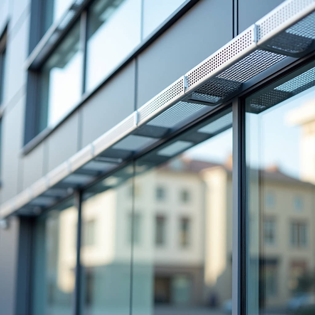
Integrating a perforated aluminium strip into unitized or stick-built curtain wall systems demands fabrication precision that exceeds standard sheet metal tolerances. Unlike generic industrial screening, architectural applications require these linear perforated elements to function as integrated weather barriers, sunshades, or decorative reveals within solid aluminium cladding panels. The primary engineering challenge lies in maintaining dimensional stability after the perforation process, as the removal of material alters the tensile characteristics and thermal expansion coefficients of the base alloy. Specifying a perforated aluminium strip for high-performance facades necessitates strict adherence to alloy temper designations, minimum border widths, and post-fabrication coating integrity tests to prevent premature failure in exterior environments.
Alloy Selection and Temper Designations for Linear Perforations
The structural viability of any perforated aluminium strip depends entirely on the base metal's mechanical properties before and after the punching operation. While 1100-H14 aluminum offers superior formability for complex curves, it lacks the yield strength required for long-span linear strips exposed to wind loads. For architectural facade applications, Alloy 5005-H34 is the industry benchmark. This magnesium-manganese alloy provides an optimal balance of moderate strength, excellent corrosion resistance, and consistent anodizing or PVDF coating response. According to ASTM B209 standards, 5005-H34 maintains a tensile strength of approximately 172 MPa (25 ksi), which is sufficient to resist deformation during the perforation process while retaining enough ductility to avoid edge cracking along the hole pattern.
Temper designation is equally critical. Using O-temper (annealed) material for a perforated aluminium strip results in excessive stretching and distortion around each punch point, leading to a wavy, non-planar surface that cannot be flattened during panel assembly. Conversely, H38 or fully hard tempers are prone to fracturing at the ligament points between holes. The H34 strain-hardened temper represents the specific manufacturing sweet spot where the grain structure has been stabilized through cold working and partial annealing. Procurement teams must verify mill test certificates to confirm the temper, as substituting H32 or H36 can alter the flatness tolerance by up to 1.5mm over a 3-meter length, causing alignment issues during curtain wall glazing installation.
Calculating Open Area and Structural Reduction
The percentage of open area directly dictates both the aerodynamic performance and the residual structural capacity of the strip. In facade engineering, this is not merely an aesthetic choice but a load-bearing calculation. When specifying a perforated aluminium strip as a sunshade or ventilation baffle, engineers must apply a reduction factor to the section modulus based on the void ratio. A standard staggered 60-degree pattern with 5mm holes and 7mm centers yields approximately 46% open area, reducing the effective moment of inertia by nearly half compared to solid stock.
- Low Open Area (10-25%): Suitable for decorative reveals and acoustic dampening backing; minimal impact on structural stiffness; allows for thinner gauges (1.6mm - 2.0mm).
- Medium Open Area (30-50%): Standard range for solar shading and privacy screens; requires 2.5mm - 3.0mm thickness to maintain rigidity; significant wind load reduction benefits.
- High Open Area (50-70%): Used for ventilation intake grilles and heavy screening; demands reinforced edges or thicker base material (3.0mm+); highly susceptible to oil-canning if unsupported.
For any perforated aluminium strip exceeding 60% open area, it is mandatory to increase the unperforated border width or add structural stiffeners. Without these reinforcements, thermal cycling will induce permanent plastic deformation at the mounting points. Engineering calculations should reference local wind code requirements, applying the appropriate gust effect factors to the reduced net area rather than the gross projected area.
Fabrication Tolerances and Edge Integrity Standards
Precision in manufacturing distinguishes architectural-grade components from commodity hardware. The tolerance stack-up for a perforated aluminium strip installed within a curtain wall system is unforgiving. Standard commercial perforating tolerances of ±0.5mm are often insufficient for unitized framing systems where gasket compression relies on tight fits. Architectural specifications should mandate tighter controls: hole diameter tolerance of ±0.1mm, pitch tolerance of ±0.15mm per meter, and overall length tolerance of +0/-1mm. These parameters ensure that when multiple strips are joined end-to-end across a facade elevation, the pattern remains visually continuous without visible misalignment.
Edge quality is another frequent point of failure. The shearing action of CNC turret punches creates burrs and micro-fractures along the perimeter of each hole. If left untreated, these rough edges become initiation points for coating delamination and filiform corrosion. Best practice requires a secondary deburring and edge-radiusing operation after perforation. For PVDF-coated systems, the edge radius should be at least 0.3mm to ensure adequate paint wrap-around. Sharp 90-degree internal corners at hole edges cannot retain sufficient film thickness during liquid coating application, leaving bare metal exposed to UV radiation and moisture. Suppliers like Futeng® typically employ vibratory tumbling or specialized brush-deburring lines specifically calibrated for thin-gauge architectural strips to achieve this edge condition consistently before the pretreatment stage.
Flatness and Camber Limitations
Perforation inherently introduces stress imbalances that manifest as camber (longitudinal bow) or cross-bow (transverse curvature). Controlling these distortions requires active leveling during the coil processing stage. Acceptable flatness criteria for architectural perforated aluminium strip should align with AAMA 2603 guidelines for extruded and formed aluminum products. A practical field acceptance criterion is no more than 2mm deviation from true plane when laid on a flat inspection table, measured at the center of a 2.4m span. Exceeding this limit forces installers to mechanically straighten the strip during fixing, introducing locked-in stresses that may release over time as temperatures fluctuate, causing the facade to appear rippled under raking light.
| Parameter | Standard Industrial Tolerance | Architectural Facade Tolerance | Critical Failure Threshold |
|---|---|---|---|
| Hole Diameter | ±0.25 mm | ±0.10 mm | >±0.30 mm (Visual Defect) |
| Pitch / Spacing | ±0.40 mm / m | ±0.15 mm / m | >±0.50 mm / m (Pattern Mismatch) |
| Strip Width | +1.0 / -0.5 mm | +0.2 / -0.2 mm | >±0.5 mm (Gasket Compression Loss) |
| Longitudinal Camber | 3 mm / 2.4 m | 1.5 mm / 2.4 m | >3 mm / 2.4 m (Installation Binding) |
| Burr Height | < 0.3 mm | < 0.1 mm (Deburred) | >0.2 mm (Coating Adhesion Risk) |
Coating System Compatibility and Pretreatment Protocols
The longevity of a perforated aluminium strip in exterior service is determined by the interface between the substrate and the finish. The increased surface area created by perforations amplifies the importance of proper chemical pretreatment. Standard chromate conversion coatings provide adequate protection for interior use, but exterior architectural applications demand fluorocarbon polymer systems meeting ISO 2360 testing protocols. The total dry film thickness (DFT) for PVDF systems should be maintained at 25-30 microns minimum, with particular attention paid to coverage inside the perforations. Electrostatic spray application naturally struggles to coat recessed surfaces; therefore, coil-coated perforated aluminium strip often provides superior and more uniform coverage on hole walls compared to post-painted batch processes.
Adhesion testing becomes more complex with perforated substrates. Cross-hatch tape tests performed only on the flat face do not guarantee performance at the hole edges where stress concentrations are highest. Quality assurance protocols should include adhesion checks specifically at the perforation boundaries using magnified visual inspection and, where possible, localized pull-off testing on sacrificial samples. Filiform corrosion resistance testing per ASTM D2803 should extend to 1000 hours minimum for coastal or high-humidity environments, evaluating both the flat surface and the perforated zones. Any sign of undercutting at hole edges during accelerated aging indicates inadequate pretreatment rinsing or insufficient primer coverage in the recessed areas.
Thermal Movement and Fixing Detail Design
Aluminum expands at approximately 23.6 µm/m·°C. For a 4-meter continuous run of perforated aluminium strip subjected to a 60°C seasonal temperature differential, theoretical movement exceeds 5.6mm. Rigidly fixing both ends of such a component guarantees buckling or fastener shear failure. Installation details must accommodate this movement through slotted holes, floating clips, or expansion joints spaced at maximum 3-meter intervals. The presence of perforations complicates this requirement because the net cross-sectional area available to transfer shear forces at connection points is reduced. Connection design must account for the weakened section at the fixings, ensuring that bearing stress on the remaining ligaments does not exceed 30% of the alloy's yield strength under combined thermal and wind loading.
Furthermore, differential thermal expansion between the perforated aluminium strip and adjacent materials (glass, steel mullions, concrete anchors) must be isolated. Direct contact between dissimilar metals in the presence of electrolytes leads to galvanic corrosion. All fixings should utilize stainless steel hardware with insulating washers or neoprene gaskets. The perforation pattern itself can influence thermal behavior; high-open-area strips heat up and cool down faster than solid sections due to increased convective airflow through the voids. This rapid thermal cycling can accelerate fatigue at restraint points if the detailing does not allow completely friction-free movement.
Quality Verification and Supply Chain Considerations
Sourcing perforated aluminium strip for critical facade elements requires validation beyond standard mill certificates. Reputable suppliers should provide sample panels demonstrating actual production tolerances, edge finish quality, and coating coverage within holes. Requesting a "first article inspection" report that documents measurements from the initial production run establishes a baseline for mass production consistency. Key metrics to verify include pattern registration relative to strip edges, consistency of open area percentage across the width, and absence of roll marks or handling damage that could compromise the finish.
Packaging and logistics also impact final quality. Perforated strips are significantly more vulnerable to bending and surface abrasion than solid sheets due to their reduced stiffness and textured surface. Interleaving paper alone is insufficient; individual polyethylene sleeving combined with rigid cardboard or timber crating is necessary to prevent transit damage. Bundles should be clearly marked with orientation arrows and stored horizontally on level supports to prevent gravity-induced sagging. On-site storage conditions must protect the material from cement dust, welding spatter, and alkaline runoff from fresh concrete, all of which can permanently stain or etch PVDF finishes even before installation is complete.
Successful integration of perforated aluminium strip into architectural facades hinges on treating it as a precision-engineered component rather than a commodity screen product. By specifying appropriate alloy tempers, enforcing architectural-grade fabrication tolerances, validating coating integrity at perforation edges, and designing connections that respect thermal dynamics, project teams can achieve durable, high-performance results that meet both aesthetic intent and technical performance requirements. Early engagement with specialized fabricators during the design development phase prevents costly redesigns and ensures that the specified perforation patterns are manufacturable within the necessary tolerance envelope for curtain wall compatibility.