Structural Integrity And Wind Load Design For Perforated Aluminium Panels Facade Systems
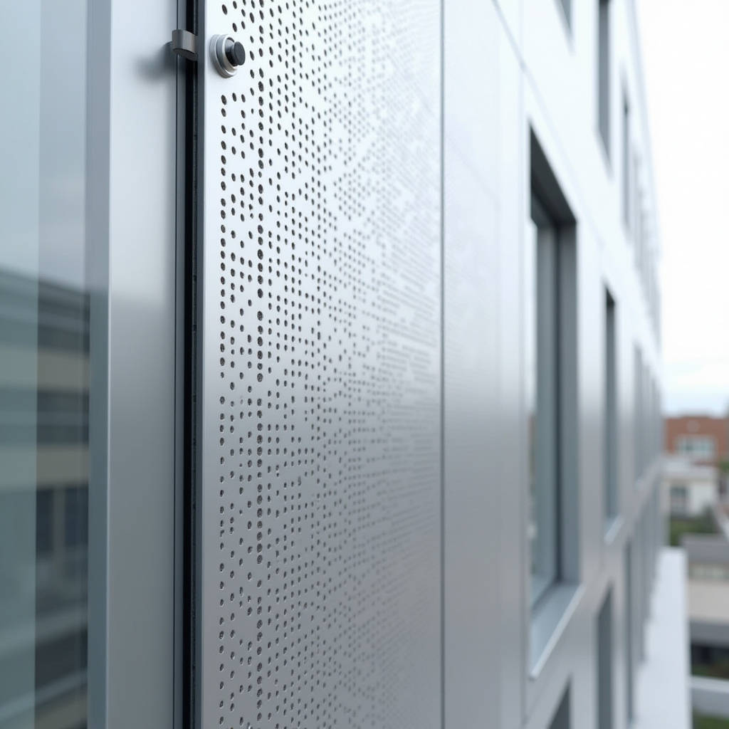
Specifying a perforated aluminium panels facade requires moving beyond aesthetic considerations to address fundamental structural engineering challenges. While the visual permeability of punched patterns defines the architectural intent, the reduction in material cross-section directly impacts wind load resistance and panel stiffness. Contractors and architects must calculate net pressure coefficients based on specific open area ratios rather than relying on standard solid sheet data. Failure to account for these variables often leads to excessive deflection, fastener fatigue, or catastrophic system failure under extreme weather events. This technical overview examines the critical relationship between perforation geometry and structural performance in solid aluminium cladding, providing actionable data for safe facade engineering and compliance with international building codes.
The Physics of Open Area Ratio and Wind Pressure
The primary distinction between solid aluminium cladding and a perforated aluminium panels facade lies in aerodynamic behavior. When wind strikes a solid surface, it creates uniform positive pressure on the windward face and suction on the leeward side. Perforations alter this dynamic significantly. Air passes through the apertures, equalizing pressure to varying degrees depending on the porosity of the pattern. This phenomenon reduces the overall drag coefficient but introduces complex localized turbulence around hole edges.
Engineering standards such as ASTM E330 provide test methods for determining structural performance, yet they do not automatically adjust design values for custom perforation layouts. The "Open Area Ratio" (OAR) is the governing metric. A panel with 20% OAR behaves structurally different from one with 50% OAR. High-porosity facades may experience reduced global wind loads, but the remaining solid ligaments between holes bear concentrated stress. If the ligament width falls below critical thresholds relative to plate thickness, the metal yields locally before the panel reaches its theoretical span capacity.
For procurement managers and engineers, this means requesting specific structural calculations for each unique pattern. Generic load-span tables for solid 3mm aluminium are invalid for perforated variants. The effective moment of inertia decreases non-linearly as material is removed. Suppliers must provide verified testing data or finite element analysis (FEA) reports demonstrating that the specific perforated configuration meets project-specific ultimate limit state (ULS) and serviceability limit state (SLS) requirements.
Material Selection: Alloy Temper and Thickness Constraints
Solid aluminium cladding for exterior perforated applications typically utilizes AA1100-H14, AA3003-H14, or AA5005-H14 alloys. The choice dictates formability and strength. AA1100 offers superior ductility for deep-drawn or complex folded perforated shapes but possesses lower yield strength. AA3003 and AA5005 provide higher mechanical strength, making them preferable for large-format perforated aluminium panels facade systems subjected to high wind zones.
Thickness selection correlates directly with perforation density. As material is removed, the equivalent structural thickness diminishes. A common industry error is specifying 2.0mm solid aluminium for a facade and assuming the same gauge suffices for a 40% perforated version. In reality, achieving identical stiffness might require upgrading to 2.5mm or 3.0mm base material. The following table illustrates approximate equivalent stiffness adjustments based on open area percentages for AA3003-H14 alloy:
| Base Thickness (mm) | Open Area Ratio (%) | Effective Structural Factor | Recommended Min. Thickness for Equivalent Stiffness | Max. Unsupported Span (Approx.) |
|---|---|---|---|---|
| 2.0 | 0% (Solid) | 1.00 | 2.0 mm | 600 mm |
| 2.0 | 20% | 0.85 | 2.5 mm | 550 mm |
| 2.0 | 40% | 0.70 | 3.0 mm | 450 mm |
| 2.5 | 20% | 0.88 | 2.5 mm | 700 mm |
| 2.5 | 40% | 0.75 | 3.0 mm | 600 mm |
| 3.0 | 40% | 0.80 | 3.0 mm | 750 mm |
Note that these values are indicative. Actual performance depends on hole shape, pitch arrangement, and edge conditions. Circular holes generally distribute stress more evenly than square or slotted openings, which create stress concentrations at corners. Specifiers should mandate minimum corner radii for non-circular perforations to prevent crack initiation during fabrication or thermal cycling.
Reinforcement Strategies for Large Format Panels
Architects frequently desire monolithic appearances with minimal visible joints, pushing panel dimensions beyond natural stiffness limits. For a perforated aluminium panels facade, reinforcement becomes mandatory when spans exceed 600-800mm depending on gauge and OAR. Welded back-stiffeners are the industry standard solution, but their implementation requires precision.
Stiffener spacing must align with the perforation pattern where possible. Placing a welded stud directly behind a cluster of holes weakens the section further. Optimal placement positions stiffeners along solid bands of metal. Aluminum studs, typically extruded profiles or bent channels, are fusion-welded to the panel rear using capacitor discharge or TIG welding. Post-weld heat treatment is rarely feasible for field-installed cladding, so weld zone softening must be factored into structural models. The heat-affected zone (HAZ) in H14 temper aluminium can lose up to 30% of its yield strength.
An alternative gaining traction involves CNC-folded integral returns. By folding the panel edges and creating intermediate box-form ribs through precision braking, manufacturers increase section modulus without adding separate welded components. This method maintains consistent metallurgical properties across the entire assembly and eliminates HAZ concerns. However, it restricts geometric freedom compared to welded stiffeners. Projects combining complex curvature with high perforation rates typically necessitate welded reinforcement despite the thermal penalties.
Coating Durability on Perforated Edges
The perforation process exposes raw aluminium edges inside every hole. These cut surfaces represent potential corrosion initiation points if not properly treated. Standard coil-coated aluminium arrives with painted faces but bare edges after punching. Post-perforation pretreatment and coating application is essential for long-term durability in coastal or industrial environments.
PVDF (Polyvinylidene Fluoride) coatings meeting AAMA 2605 specifications remain the benchmark for exterior perforated aluminium panels facade systems. Minimum film thickness should be 25 microns on exposed surfaces. Crucially, specifiers must verify edge coverage. Electrostatic spray application tends to wrap paint around sharp edges due to the Faraday cage effect, but internal hole surfaces may receive insufficient build. Dip-coating or specialized multi-pass spraying ensures complete encapsulation of perforation interiors.
Anodizing presents another viable finish, particularly for metallic aesthetics. Type II sulfuric acid anodizing per ISO 7599 provides excellent edge protection since the oxide layer grows integrally from the substrate. Unlike organic coatings, anodized layers cover all exposed surfaces uniformly regardless of geometry complexity. However, color consistency across large batches of perforated panels proves more challenging with anodizing than with PVDF. Mockup approval and range samples become mandatory quality control steps.
Acoustic Performance Considerations
Beyond structure and weathering, perforated aluminium panels facade systems frequently serve acoustic functions. The Helmholtz resonator principle applies when perforated metal mounts over an air cavity backed by sound-absorbing insulation. Absorption peaks occur at frequencies determined by hole diameter, OAR, panel thickness, and cavity depth.
Facade-integrated acoustic treatment differs from interior ceiling applications. Exterior noise sources (traffic, HVAC equipment) occupy lower frequency bands requiring deeper cavities and larger perforations. Typical facade configurations utilize 3-5mm holes with 15-25% OAR and 50-100mm air gaps. Mineral wool backing must be hydrophobic and UV-resistant if exposed through perforations. Facing fabrics on insulation prevent fiber erosion while maintaining acoustic transparency.
Manufacturers like Futeng® increasingly provide tested NRC (Noise Reduction Coefficient) data for specific perforated configurations rather than generic claims. Requesting third-party lab verification per ISO 354 prevents post-installation disappointment. Remember that structural stiffeners reduce effective cavity volume and alter acoustic tuning. Coordinate reinforcement layout with acoustic consultants early in design development to avoid compromising dual-purpose performance.
Installation Tolerances and Thermal Movement
Aluminium expands approximately 2.4mm per meter per 100°C temperature change. A 3-meter tall perforated panel experiences nearly 7mm vertical movement between winter night and summer day extremes. Fixing systems must accommodate this differential without inducing buckling or fastener shear.
Slotted holes at attachment points allow controlled translation. Fixed-point anchors should concentrate at panel centers or designated restraint locations, with remaining connections serving as sliding bearings. For perforated aluminium panels facade assemblies, slot orientation matters critically. Vertical slots permit thermal expansion but resist gravity; horizontal slots accommodate lateral wind-induced movement. Mixing slot directions within a single panel requires careful engineering to prevent binding.
Tolerance stack-up compounds rapidly in modular facade systems. Manufacturing tolerances for perforated panels typically run ±1.0mm on dimensions and ±0.5mm on flatness. Substructure alignment tolerances add another ±2-3mm. Combined deviations can exceed joint sealant capabilities or reveal misalignment visually. Establishing comprehensive tolerance budgets during shop drawing review prevents costly site rework. Digital twin modeling and prefabricated subassembly verification mitigate risks associated with complex perforated geometries.
Fire Safety and Code Compliance
Solid aluminium cladding carries inherent fire safety advantages over composite alternatives. Pure aluminium melts at approximately 660°C but does not contribute fuel load or produce toxic smoke. Perforated variants maintain this classification provided backing materials also meet combustibility requirements. Insulation, vapor barriers, and acoustic infills within the facade cavity must comply with local fire codes.
Perforations affect fire compartmentation. Openings facilitate airflow that can accelerate flame spread within cavities. Fire stops and cavity barriers installed behind perforated zones require special detailing to maintain integrity while accommodating ventilation needs. Intumescent seals that expand upon heat exposure offer solutions for maintaining fire ratings without permanently blocking designed airflow paths. Always verify assembly-level fire test certification rather than relying solely on individual material classifications.
Procurement and Quality Verification Protocols
Sourcing perforated aluminium panels facade systems demands rigorous supplier qualification. Request mill certificates confirming alloy grade and temper for every production batch. Verify coating thickness via dry film gauges on sample coupons representing actual perforated product, not just flat test panels. Conduct adhesion testing per ASTM D3359 on finished goods to confirm pretreatment effectiveness on cut edges.
Dimensional accuracy checks should employ optical scanning or coordinate measuring machines for complex patterns rather than manual tape measurements. Pattern registration errors accumulate visibly across facade elevations. Require pre-shipment assembly trials for critical interface details. Photographic documentation of packing methods prevents transit damage disputes. Clear contractual language defining acceptance criteria for perforation burrs, coating holidays, and flatness deviations establishes objective quality benchmarks before fabrication commences.
Successful perforated aluminium facade projects balance artistic vision with engineering rigor. Treating perforations as structural modifications rather than mere decorative overlays ensures long-term performance matching initial design intent. Collaboration between architects, facade engineers, and specialized manufacturers from concept stage through installation remains the most reliable path to achieving both aesthetic excellence and technical compliance in contemporary metal cladding applications.