Perforated ACP Sheet Design Intent Realized Through Solid Aluminium Cladding Panels
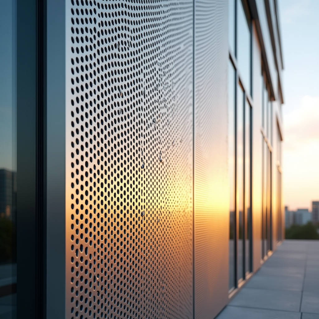
Architects frequently specify a perforated acp sheet to achieve intricate facade patterns and dynamic light filtration, yet the long-term performance requirements of commercial projects often demand superior material properties. Solid aluminium cladding panels provide an engineered solution that replicates the visual precision of composite materials while offering enhanced structural rigidity, fire safety, and coating longevity. Unlike composite alternatives containing polyethylene cores, solid aluminium sheets eliminate delamination risks and maintain dimensional stability under extreme thermal cycling. This technical analysis examines how fabricators translate complex perforation designs into durable monolithic metal systems, focusing on CNC tolerances, wind load engineering, and PVDF coating specifications necessary for high-performance building envelopes.
Material Distinctions Between Composite and Solid Perforated Systems
The search for a perforated acp sheet typically originates from aesthetic intent rather than structural necessity. Understanding the fundamental differences between Aluminium Composite Panels (ACP) and solid aluminium cladding is critical for procurement teams evaluating lifecycle costs. ACP consists of two thin aluminium skins bonded to a thermoplastic core, usually ranging from 0.3mm to 0.5mm per skin. While this construction allows for cost-effective flat panel production, the perforation process exposes the core material at every hole edge. In exterior applications, these exposed edges become potential pathways for moisture ingress and UV degradation of the core over decades of service.
Solid aluminium cladding panels, manufactured from 2.0mm, 2.5mm, or 3.0mm alloy sheets (typically AA1100, AA3003, or AA5005 series), present a homogeneous cross-section throughout the perforated area. When CNC machinery punches holes through solid aluminium, the resulting edge remains pure metal, fully compatible with post-fabrication liquid paint application. This homogeneity ensures that the protective PVDF coating encapsulates the entire perforation perimeter, providing uniform corrosion resistance that composite materials cannot match. For projects in coastal environments or areas with high industrial pollution, this edge protection significantly extends the maintenance interval and preserves facade integrity.
Fire performance represents another decisive factor. Many jurisdictions now restrict combustible core materials in high-rise cladding following updated NFPA 285 and EN 13501-1 standards. Solid aluminium panels are inherently non-combustible (Euroclass A1), eliminating the need for additional fire-stopping measures around perforated zones where composite cores might otherwise require intumescent sealants or edge banding treatments.
CNC Perforation Tolerances and Pattern Feasibility
Translating digital perforation patterns into physical metal requires precise understanding of fabrication limitations. Architects designing with the visual language of a perforated acp sheet must account for tooling constraints specific to solid aluminium thickness. The general engineering rule dictates that minimum hole diameter should equal or exceed the material thickness; attempting to punch 1.5mm holes in 2.0mm plate causes excessive tool wear, burr formation, and sheet distortion. For intricate parametric designs requiring smaller apertures, laser cutting becomes necessary, though this increases unit cost and introduces heat-affected zones that require deburring before coating.
Open area percentage directly impacts both structural capacity and acoustic/ventilation performance. Industry best practice limits open area to 40% for structural facade panels without secondary reinforcement. Exceeding this threshold reduces the effective moment of inertia, necessitating closer stiffener spacing or increased base metal thickness. Futeng® fabrication protocols typically recommend maintaining a minimum ligament width (material between adjacent holes) equal to 1.5 times the sheet thickness to prevent tearing during handling and installation. These parameters ensure that the delicate appearance of fine perforation does not compromise panel survivability during shipping or wind loading events.
Nesting efficiency also influences project economics. Unlike standard rectangular cladding, perforated sheets generate significant scrap material. Advanced nesting software can optimize pattern placement to reduce waste by 15-20%, but designers should be aware that irregular hole distributions or gradient patterns inherently produce lower yield rates. Specifying standardized hole sizes and modular grid alignments facilitates batch processing and reduces tooling changeover time, directly impacting lead times for large-scale facade orders.
Recommended Hole-to-Thickness Ratios for Solid Aluminium
| Sheet Thickness (mm) | Min Hole Diameter - Punch (mm) | Min Hole Diameter - Laser (mm) | Max Open Area (%) | Stiffener Spacing @ 40% Open |
|---|---|---|---|---|
| 2.0 | 2.0 | 1.2 | 40 | 450mm |
| 2.5 | 2.5 | 1.5 | 38 | 500mm |
| 3.0 | 3.0 | 1.8 | 35 | 600mm |
Wind Load Engineering for Perforated Monolithic Panels
Perforations fundamentally alter the aerodynamic behavior of cladding panels. Wind pressure coefficients derived from solid panel testing do not apply to perforated surfaces because airflow through the openings equalizes partial pressures across the panel face. According to ASCE 7-22 Chapter 30, perforated walls with open areas exceeding 10% require specialized wind tunnel testing or computational fluid dynamics (CFD) analysis to determine accurate design loads. Relying on standard solid-panel coefficients can lead to either unsafe under-design or costly over-engineering.
For preliminary sizing, engineers may apply reduction factors based on porosity. Research published in the Journal of Wind Engineering indicates that panels with 20-30% open area experience approximately 60-70% of the net pressure applied to equivalent solid surfaces. However, this reduction applies only to overall panel bending; local stresses around individual perforations can actually increase due to stress concentration effects. Finite element analysis (FEA) modeling should verify that peak localized stresses at hole edges remain below the allowable yield strength of the aluminium alloy under factored wind loads, typically using a safety factor of 1.65 per Aluminium Association Design Manual.
Stiffener integration becomes more complex with perforated geometry. Traditional welded back-stiffeners cannot pass through open areas, requiring segmented reinforcement or perimeter-only framing. Some fabricators employ structural silicone bonding of stiffeners to avoid welding distortion near perforated zones, though this method requires verification of adhesive shear capacity under sustained wind suction. The connection design between panel and substructure must also account for reduced torsional rigidity; four-point fixings are generally preferred over two-point hanging systems for perforated solid aluminium to prevent racking deformation.
PVDF Coating Performance on Perforated Edges
The durability of any metal facade system depends on complete coating coverage, and perforations represent the most vulnerable points in the finish envelope. Liquid-applied PVDF (polyvinylidene fluoride) coatings, meeting AAMA 2605 specifications, provide superior edge encapsulation compared to coil-coated finishes. During spray application, electrostatic attraction draws paint into hole interiors, achieving film thickness on vertical perforation walls that approaches the nominal surface build. Coil-coated materials, by contrast, leave cut edges completely bare unless post-painted, creating immediate corrosion initiation sites.
Minimum dry film thickness (DFT) on perforated solid aluminium should be verified at multiple locations including hole edges, not just flat surfaces. Quality control protocols typically mandate 25μm primer plus 25μm topcoat on all exposed surfaces, with spot checks using magnetic or eddy-current gauges inserted into sample perforations. Accelerated weathering tests per ASTM G154 should demonstrate less than 5 Delta E color shift and no chalking after 4000 hours QUV exposure, validating that the coating formulation maintains adhesion and pigment stability even on geometrically complex substrates.
Color matching presents additional challenges for perforated panels. The visual perception of color shifts when viewing through overlapping layers of perforated metal, especially with backing membranes or insulation visible behind. Specifiers should request physical mockups with actual perforation patterns and intended backlighting conditions before approving production runs. Metallic and pearlescent pigments exhibit pronounced directional variation in perforated configurations due to altered light reflection angles; solid colors or matte finishes generally provide more predictable appearance across varied viewing geometries.
Installation Considerations and Thermal Movement
Solid aluminium exhibits a coefficient of thermal expansion of 23.4 × 10⁻⁶ /°C, meaning a 3-meter panel expands approximately 2.8mm over a 40°C temperature range. Perforated panels complicate accommodation of this movement because the open areas reduce continuous bearing surface at fastener points. Slotted holes or floating clip systems must be sized to allow full thermal travel without binding, while still providing adequate pull-through resistance. Fastener head diameter should exceed slot width by at least 3mm to prevent disengagement during extreme contraction events.
Handling and storage protocols differ significantly from composite materials. Perforated solid aluminium lacks the core damping that gives ACP its rigidity, making large-format perforated sheets susceptible to permanent deformation if lifted improperly. Fabricators should specify lifting points aligned with stiffener locations, and transport frames must support panels at maximum 600mm intervals to prevent sagging. On-site storage requires flat, covered staging away from cement dust and alkaline runoff, which can stain unprotected aluminium within hours of contact.
Maintenance access planning should account for the fragility of perforated zones. Window washing equipment, scaffolding ties, and temporary protection must never bear directly on perforated areas. Facility managers need documented cleaning procedures specifying non-abrasive methods; pressure washing above 1500 PSI can deform thin ligaments between holes. Regular inspection schedules should focus on verifying coating integrity at perforation edges and checking fastener torque retention, as vibration through open panels can accelerate loosening compared to solid cladding installations.
Project Specification Guidance for Material Substitution
When project documentation references a perforated acp sheet but performance criteria exceed composite capabilities, specification language should facilitate approved substitution without redesign delays. Performance-based specs defining open area tolerance, wind load capacity, fire rating, and coating warranty duration enable contractors to propose solid aluminium equivalents based on verified test data rather than prescriptive material calls. Including acceptable alloy designations, temper conditions, and fabrication standards in the base bid documents prevents value-engineering proposals that sacrifice long-term durability for initial cost savings.
Sample approval processes for perforated metal should mandate submission of production-intent specimens rather than generic catalog pieces. Only samples fabricated using the same tooling, coating line, and installation hardware as the final delivery can validate color consistency, hole quality, and fit-up accuracy. Photographs of installed mockups under natural lighting provide more reliable appearance verification than laboratory-controlled color measurements, particularly for projects where the perforated screen functions as a primary architectural expression.
Successful execution of perforated metal facades requires alignment between design ambition and manufacturing reality. By treating the transition from composite specification to solid aluminium execution as an engineering optimization rather than a simple material swap, project teams can achieve the desired visual complexity while securing the structural resilience and weathering performance that modern commercial architecture demands. The result is a facade system that honors the original design intent through technically superior realization.