Engineering Solid Aluminium Building Facade Panels for Complex Geometries and Wind Loads
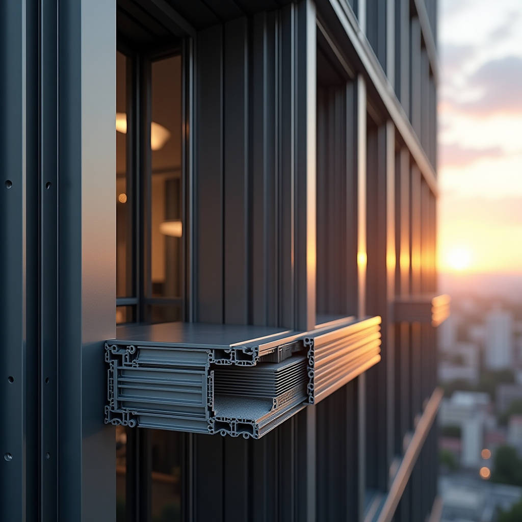
Selecting an aluminium building facade system involves far more than aesthetic preference; it demands rigorous engineering validation to ensure structural integrity under dynamic environmental loads. For architects and contractors specifying solid aluminium cladding panels, the primary technical challenges center on managing wind pressure differentials, accommodating thermal movement, and achieving complex geometric forms without compromising material performance. Unlike composite alternatives, solid aluminium sheets offer superior formability and non-combustible properties essential for high-rise and public infrastructure projects. This analysis focuses on the mechanical behavior of 2mm to 4mm solid aluminium plates within ventilated rainscreen assemblies, addressing critical fabrication tolerances, alloy selection criteria, and anchorage strategies that define long-term facade durability and safety compliance in demanding architectural applications.
Structural Performance and Wind Load Engineering
The structural capacity of a solid aluminium building facade is governed by the interaction between panel thickness, stiffener configuration, and support span. Wind load resistance is not an intrinsic property of the material alone but a system-level performance metric derived from plate bending theory and empirical testing. According to ASTM B209 standards for aluminum-alloy sheet and plate, the allowable stress design must account for both positive (inward) and negative (outward/suction) pressures, which often dictate the fastening schedule and edge detailing.
For solid aluminium panels ranging from 2.5mm to 3.0mm thickness, unreinforced spans are typically limited to 600mm to 750mm depending on the specific alloy temper. Exceeding these limits necessitates the integration of welded or mechanically fixed stiffeners. These reinforcements transform the flat plate into a composite structural element, significantly increasing the moment of inertia and reducing deflection. Engineering calculations must verify that maximum deflection under service loads does not exceed L/180 or 3mm, whichever is less, to prevent permanent deformation or coating fracture. The placement of stiffeners is critical; they should be positioned at points of maximum bending moment and aligned with fixing brackets to create direct load paths back to the primary structure.
Alloy Selection for Structural Demands
Material specification directly influences the engineering envelope of the facade. Two alloys dominate the solid aluminium cladding sector: AA5754-H22 and AA3003-H14/H24. Understanding their distinct mechanical profiles is essential for value engineering and performance assurance.
- AA5754-H22: An aluminum-magnesium alloy offering higher tensile strength (typically 190-240 MPa) and superior corrosion resistance in marine or industrial atmospheres. Its higher yield strength allows for wider bracket spacing or thinner gauges in high-wind zones, making it the preferred choice for coastal high-rises and exposed facades.
- AA3003-H14/H24: A manganese-alloyed grade with moderate strength (110-170 MPa) but exceptional formability. It is ideal for projects requiring tight radii, deep draws, or complex double-curvature geometries where 5xxx series alloys might crack during fabrication. While structurally adequate for most urban environments, it requires closer support spacing compared to 5754.
Specifiers must balance formability against structural efficiency. Using AA3003 for large-format flat panels may result in unnecessary stiffener density, whereas using AA5754 for intricate folded details risks fabrication defects. Material certificates complying with EN 485-2 or ASTM B209 should be mandatory deliverables to verify temper and mechanical properties before fabrication commences.
Fabrication Precision and Geometric Tolerances
The transition from digital model to physical reality introduces variables that can compromise facade performance if not managed through strict fabrication protocols. Solid aluminium panels are susceptible to springback, welding distortion, and handling damage, all of which affect installation fit-up and visual quality. Establishing clear tolerance benchmarks in the procurement specification prevents costly site rework and delays.
CNC routing and folding machinery provide the baseline accuracy, but manual processes like welding and grinding introduce variability. For folded cassettes, the internal corner radius should never be less than 1.5 times the material thickness to avoid micro-cracking in the H14/H22 tempers. Welded stiffeners require particular attention; improper heat input causes localized annealing and warping. Best practice dictates using pulsed MIG or TIG welding with controlled heat sinks, followed by mechanical straightening or roller leveling while the panel is still warm. Post-fabrication inspection should verify flatness deviations do not exceed 2mm over any 1-meter straightedge, as per industry norms referenced in AAMA metal curtain wall manuals.
Managing Thermal Expansion in Large Formats
Aluminium has a coefficient of thermal expansion approximately twice that of steel or concrete (23.6 × 10⁻⁶ /°C). On a 3-meter tall panel subjected to a 60°C seasonal temperature differential, theoretical linear movement exceeds 4mm. Restraining this movement induces compressive buckling in summer or tensile failure at fixings in winter. The aluminium building facade system must incorporate designed accommodation for this differential movement.
Fixed-point and sliding-point bracket arrangements are the standard engineering solution. Typically, one anchor per panel is designated as the fixed point, usually near the geometric center or top-center, while all other anchors utilize slotted holes oriented vertically to permit free vertical translation. Horizontal slots accommodate lateral expansion. The slot length must be calculated based on the panel dimension, expected temperature range, and installation temperature, plus a safety margin for construction tolerances. Isolating dissimilar metals with EPDM or nylon shims prevents galvanic corrosion and reduces friction noise during thermal cycling. Ignoring these details leads to audible clicking, visible oil-canning, and eventual fastener fatigue.
Coating Systems and Environmental Durability
The longevity of a solid aluminium building facade depends entirely on the coating system's ability to resist UV degradation, chemical attack, and mechanical abrasion. While the aluminium substrate provides corrosion resistance, the finish protects both the metal and the architectural intent. Fluoropolymer coatings remain the benchmark for exterior cladding, but performance varies significantly based on resin chemistry and application parameters.
PVDF (Polyvinylidene Fluoride) coatings containing minimum 70% Kynar 500® or Hylar 5000® resins meet AAMA 2605 specifications for superior performance. These systems typically achieve 20-30 years of color retention (ΔE < 5 Hunter units) and chalk resistance (ASTM D4214 rating ≥ 8) in harsh environments. Total dry film thickness should be verified at 25-30 microns minimum, applied over a chromate-free pretreatment and primer layer. Lower-grade polyester or FEVE coatings may offer initial cost savings but often fail to maintain gloss and color stability beyond 10-15 years in exposed applications.
| Performance Parameter | AAMA 2605 (PVDF) | AAMA 2604 (High-Perf Polyester) | AAMA 2603 (Standard Polyester) |
|---|---|---|---|
| Color Retention (Years) | 20-30 (ΔE < 5) | 10-15 (ΔE < 5) | 5-7 (ΔE < 5) |
| Chalk Resistance | Rating ≥ 8 | Rating ≥ 6 | Rating ≥ 5 |
| Gloss Retention (30° @ 10yr) | > 50% | > 30% | N/A |
| Salt Spray Resistance (Hours) | 4000+ | 2000-3000 | 1000-1500 |
| Humidity Resistance (Hours) | 4000+ | 2000-3000 | 1000-1500 |
| Typical Warranty Period | 20 Years | 10 Years | 5 Years |
When sourcing solid aluminium panels, verifying the coating applicator's certification is as important as the paint brand itself. Reputable manufacturers like Futeng® maintain documented quality control records linking each batch to specific coil or spray line parameters, ensuring traceability for warranty validation. Requesting accelerated weathering test reports (QUV or Xenon arc) alongside field exposure data provides additional confidence for projects in extreme climates.
Substructure Design and Anchorage Strategy
The aluminium building facade panel is only as reliable as its supporting substructure. Rainscreen principles mandate a ventilated cavity behind the cladding to equalize pressure and manage moisture, but this cavity also houses the structural transfer mechanism. Subframe design must reconcile the irregularities of the primary structure with the precise planarity required for metal cladding.
Vertical mullions, typically extruded aluminium T-profiles or L-brackets, transfer panel loads to floor slabs or structural columns. Bracket spacing is determined by wind load calculations and slab edge conditions, commonly ranging from 900mm to 1200mm horizontally. Vertical spacing aligns with floor-to-floor heights but must include intermediate supports for tall panels to limit mullion deflection. Adjustable brackets with slotted holes allow for three-dimensional alignment compensation, absorbing construction tolerances up to ±25mm in typical systems.
Thermal bridging through metal brackets is a critical energy performance concern. Modern codes increasingly require continuous insulation layers, necessitating thermally broken bracket designs or non-conductive spacers. Stainless steel or fibre-reinforced polymer isolators reduce heat transfer while maintaining structural capacity. The substructure material must be compatible with the cladding; mixing untreated steel with aluminium creates severe galvanic risk. Powder-coated or anodized aluminium subframes are standard, with stainless steel fasteners specified throughout to prevent bimetallic corrosion.
Fire Safety and Non-Combustibility Compliance
Regulatory scrutiny of facade materials has intensified globally following several high-profile fire incidents. Solid aluminium panels inherently satisfy non-combustibility requirements under ISO 1182 and EN 13501-1 Class A1/A2-s1,d0 classifications, unlike polyethylene-core composites. However, the complete assembly—including insulation, membranes, and sealants—must be evaluated as a system. Combustible gaskets, adhesive tapes, or foam backer rods can compromise the overall fire rating even when the primary cladding is non-combustible.
Project specifications should explicitly require full-system fire testing or engineering judgments from accredited laboratories, rather than relying solely on individual component certifications. Cavity barriers and fire stops must be integrated at every floor level and compartment boundary to prevent vertical flame spread within the rainscreen void. Documentation packages should include detailed cross-sections showing fire-stopping continuity, particularly at window reveals, parapets, and service penetrations where gaps are most likely to occur.
Installation Sequencing and Quality Assurance
Even perfectly engineered panels fail if installed incorrectly. Installation methodology should be defined in the project-specific method statement, covering lifting procedures, temporary bracing, torque settings for fasteners, and protection measures. Solid aluminium panels are relatively soft and easily scratched; protective films must remain intact until final handover, and suction lifters should be used exclusively for handling finished surfaces.
Fastener torque is frequently overlooked yet critically important. Over-tightening distorts the panel face and restricts thermal movement; under-tightening permits vibration and water ingress. Calibrated torque wrenches set to manufacturer-specified values (typically 3-5 Nm for M5/M6 screws into aluminium extrusions) ensure consistent clamp load without damage. Self-drilling screws must have approved drill points and neoprene washers sized correctly for the substrate gauge. Pull-out tests conducted on-site at project commencement validate that the selected fastener achieves required withdrawal resistance in the actual structural substrate.
Mock-up testing serves as the definitive quality gate before mass production and installation. A full-scale section including corners, windows, and transitions should be fabricated and installed to verify dimensional coordination, joint widths, sealant adhesion, and visual appearance under natural lighting. Water penetration testing per ASTM E1105 on the mock-up identifies leakage paths that shop drawings cannot predict. Lessons learned from mock-up evaluation inform adjustments to fabrication templates, bracket positions, and installation sequences, preventing systemic defects across the entire facade area.
Technical Summary for Specification
Successful delivery of a solid aluminium building facade requires integrating structural analysis, material science, fabrication precision, and installation discipline into a coherent technical package. Key takeaways for specifiers and contractors include verifying alloy and temper suitability for both forming and loading, mandating AAMA 2605 compliant fluoropolymer finishes for long-term aesthetics, designing explicit thermal movement accommodation into every panel and bracket interface, and validating fire safety at the system level rather than component level. Engaging experienced fabricators early in the design phase enables optimization of panel sizes, joint patterns, and support layouts to balance architectural vision with constructability and budget. Rigorous documentation, testing, and on-site quality verification transform theoretical performance into built reality, ensuring the facade serves its intended function safely and durably for decades.