Structural Integrity and Wind Load Management in Decorative Perforated Aluminum Sheet Facades
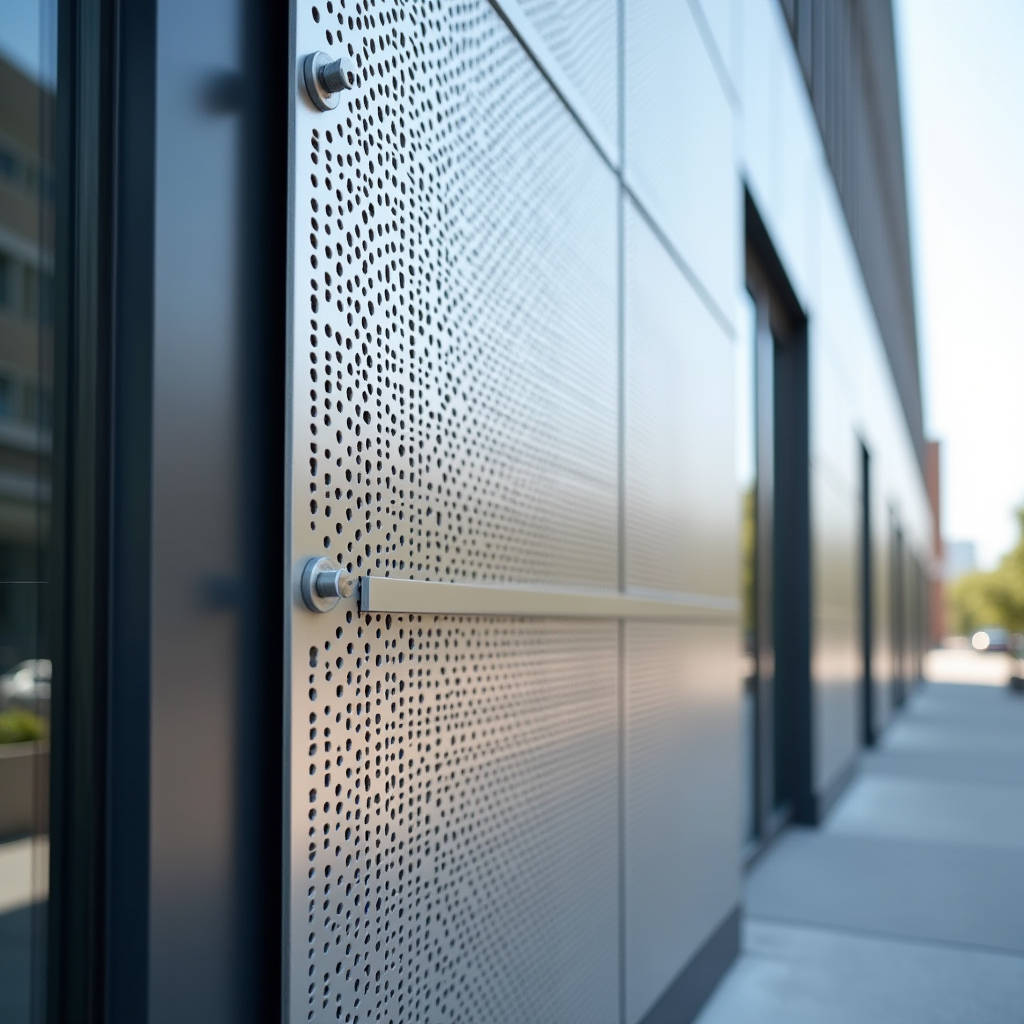
Integrating a decorative perforated aluminum sheet into a building envelope introduces complex structural variables that differ significantly from solid cladding systems. While the aesthetic appeal of custom hole patterns drives architectural specification, the physical removal of material directly reduces the panel's moment of inertia and load-bearing capacity. Engineers and procurement managers must calculate net section properties rather than relying on gross thickness specifications to prevent facade failure under negative wind pressure. This technical analysis addresses the critical intersection of open area percentages, alloy selection, and substructure spacing required to maintain structural integrity in ventilated rainscreen applications using solid aluminum panels.
Structural Capacity Reduction Due to Perforation Patterns
The primary engineering challenge when specifying a decorative perforated aluminum sheet is quantifying the strength loss caused by the voids. Standard span tables provided by manufacturers typically apply to solid sheets; applying these same parameters to perforated panels without adjustment leads to unsafe deflection or plastic deformation. The reduction in structural capacity is not linear with the open area percentage. A panel with 40% open area does not retain 60% of its original strength. Stress concentrations occur at the edges of each hole, creating localized weak points that propagate cracks under cyclic wind loading.
According to ASTM B209 standards for aluminum-alloy sheet and plate, the base mechanical properties of Alloy 5052-H32 provide a tensile strength of approximately 228 MPa. However, when perforated, the effective yield strength must be derated based on the specific hole geometry and stagger pattern. Round holes arranged in a 60-degree stagger generally offer better structural continuity than square holes in a straight grid, as the ligaments (the solid metal between holes) are more evenly distributed across the stress axis. For high-wind zones, keeping the open area below 35% is often necessary to maintain adequate safety factors without increasing panel thickness or reducing support spacing.
Calculating Net Section Modulus
Facade engineers must determine the net section modulus to verify that bending stresses remain within allowable limits. This calculation accounts for the actual metal cross-section resisting the moment. When evaluating a decorative perforated aluminum sheet for curtain wall applications, the formula for net width subtracts the sum of hole diameters along the critical failure path, plus an allowance for stress concentration factors defined in Aluminum Association Design Manual. Ignoring this step results in panels that may pass static load tests but fail under dynamic fatigue caused by vortex shedding or flutter.
- Ligament Width: Minimum solid metal between adjacent holes should exceed 1.5 times the sheet thickness to prevent tearing during fabrication and service.
- Hole-to-Edge Distance: Unperforated margins of at least 20mm are required for proper folding and edge stiffening; reducing this margin compromises the return leg's ability to transfer shear loads to the substructure.
- Pattern Orientation: Aligning the long dimension of slot patterns perpendicular to the primary support members maximizes stiffness compared to parallel orientation.
Wind Load Dynamics and Pressure Equalization
Perforated facades function differently than sealed barrier walls regarding wind pressure. A decorative perforated aluminum sheet acts as a porous screen, allowing partial pressure equalization between the exterior environment and the cavity behind the cladding. This phenomenon can reduce peak suction loads on the panel itself but increases airflow velocity through the openings, potentially causing acoustic issues or water ingress if the weather barrier is not properly detailed. The degree of pressure equalization depends directly on the porosity ratio and the compartmentalization of the air cavity.
Research cited in Natural Resources Canada building envelope guidelines indicates that for open areas exceeding 20%, the pressure differential across the panel drops significantly, shifting the structural demand from pure bending to local buckling around fastener points. Fasteners become the critical failure mode rather than mid-span deflection. Consequently, fixing center distances for perforated panels often need to be 20-30% closer than those used for equivalent solid gauges. Relying solely on adhesive bonding is insufficient for perforated systems due to the reduced contact surface area and potential for moisture accumulation within the bond line.
Cavity Ventilation and Moisture Management
While ventilation is a functional benefit of specifying a decorative perforated aluminum sheet, uncontrolled airflow carries risks. High-velocity air passing through small apertures creates venturi effects that can draw rainwater deeper into the cavity than expected. Proper detailing requires baffles or secondary drainage planes positioned behind the perforated zone. Additionally, thermal bridging through the metal fasteners becomes more pronounced as airflow increases convective heat transfer within the cavity. Thermal break pads installed between the panel returns and the substructure clips mitigate condensation risk and improve overall U-value performance.
Material Selection: Alloy 5052 vs. 3003 for Perforated Applications
Not all aluminum alloys respond identically to the perforation process. The choice between Alloy 3003 and Alloy 5052 dictates both formability and long-term durability in exposed architectural applications. While 3003 is softer and easier to punch, it lacks the mechanical reserve needed for large-format perforated panels subjected to significant wind loads. Understanding the metallurgical differences ensures the selected material aligns with both fabrication constraints and structural requirements.
| Parameter | Alloy 3003-H14 | Alloy 5052-H32 | Engineering Implication for Perforated Panels |
|---|---|---|---|
| Tensile Strength | 150 MPa | 228 MPa | 5052 offers 52% higher resistance to wind-induced bending stress. |
| Yield Strength | 145 MPa | 193 MPa | Higher yield prevents permanent deformation after extreme gust events. |
| Elongation at Break | 10% | 12% | Both allow forming, but 5052 maintains ductility post-perforation. |
| Fatigue Resistance | Moderate | High | Critical for perforated sheets experiencing cyclic vibration. |
| Marine Environment Suitability | Good | Excellent | 5052 resists salt spray corrosion at exposed hole edges superiorly. |
For any decorative perforated aluminum sheet intended for coastal projects or high-rise facades where replacement costs are prohibitive, Alloy 5052-H32 represents the industry baseline. Suppliers like Futeng® routinely stock this grade specifically for architectural perforation work because it balances punching quality with the structural reserves demanded by modern wind codes. Using 3003 in these scenarios may lower initial material cost but increases lifecycle risk through premature fatigue cracking or corrosion pitting at the raw hole edges.
Coating Adhesion Challenges on Perforated Surfaces
The finishing process for perforated aluminum presents unique quality control hurdles absent in solid sheet production. When a decorative perforated aluminum sheet undergoes PVDF (polyvinylidene fluoride) coating, the liquid paint tends to accumulate at the rim of each hole due to surface tension, creating thick beads that cure improperly. Conversely, the vertical inner walls of the holes often receive insufficient film build, leaving bare metal exposed to UV radiation and moisture. These inconsistencies compromise the warranty validity and accelerate degradation.
Manufacturers must adjust spray gun angles, flow rates, and conveyor speeds to ensure uniform coverage across both faces and the internal bore surfaces. Pre-treatment chemistry also requires modification; standard dip tanks may trap chemicals inside the holes, leading to outgassing during curing and subsequent blistering. Spray pre-treatment systems with oscillating nozzles provide better penetration and rinsing for perforated substrates. Specifiers should request cross-section microscopy reports verifying minimum film thickness on hole interiors, not just face measurements, when approving finish samples.
PVDF Film Thickness Verification
AAMA 2605-21 specifies a minimum total dry film thickness of 30 microns for PVDF coatings on architectural aluminum. For perforated products, achieving this consistently requires targeting 35-40 microns on the face to guarantee adequate coverage internally. Electrostatic application methods improve wrap-around efficiency compared to conventional air spray, reducing the "picture framing" effect around hole perimeters. Post-coating sealing of hole edges with clear lacquer adds another layer of protection but increases cost; this treatment is recommended only for highly aggressive environments or when using lighter metallic pigments prone to oxidation.
Fabrication Tolerances and Flatness Control
Perforating aluminum sheet releases residual rolling stresses, inevitably causing distortion. Maintaining flatness in a decorative perforated aluminum sheet requires proactive manufacturing strategies rather than reactive straightening. The punching sequence, tool clearance, and hold-down pressure all influence the final planarity. Excessive curl or waviness becomes visually amplified once installed on a facade, especially under raking sunlight conditions.
Industry best practice involves alternating punch directions and using progressive die sets that balance lateral forces during the piercing stroke. After perforation, roller leveling passes restore flatness before cutting to size and folding. Allowable flatness deviation for architectural perforated panels typically ranges from 2mm to 3mm over a 1.5m span, tighter than industrial screening tolerances but looser than solid cassettes. Acknowledging this inherent limitation during the design phase prevents unrealistic expectations. Substructure systems incorporating adjustable stand-offs accommodate minor variations without inducing stress into the panel assembly.
Edge Detailing and Return Leg Integrity
Folding perforated material demands careful attention to bend radii and setback distances. Holes located too close to the bend line deform during pressing, distorting the visual pattern and weakening the corner. A minimum unperforated border of 25mm allows clean brake forming while preserving structural continuity at the edges. Where patterns must extend to the visible edge, laser-cut borders provide cleaner transitions than punched margins but add processing expense. Welded corners on perforated cassettes require backer strips to bridge the voids; otherwise, weld burn-through and inconsistent penetration create structural defects and aesthetic blemishes.
Installation Protocols for Perforated Rainscreens
Site handling of perforated aluminum differs fundamentally from solid panels. The open structure makes the material susceptible to damage from gripping tools, finger oils, and debris ingress during storage. Installation crews must use non-marring suction lifters designed for porous surfaces; standard vacuum cups lose seal instantly on perforated stock. Mechanical lifting clamps with padded jaws offer a reliable alternative, provided contact points align with solid ligament zones rather than spanning multiple holes.
Fastener selection requires matching the coefficient of thermal expansion and galvanic compatibility. Stainless steel A4-80 screws with neoprene washers prevent staining and accommodate differential movement. Over-tightening fasteners against perforated panels crushes the ligaments and induces local buckling; torque-limiting drivers set to manufacturer specifications eliminate this common installation error. Expansion slots in mounting brackets allow longitudinal movement independent of the panel perforation pattern, preventing stress buildup during thermal cycling. Regular inspection schedules should focus on fastener loosening and coating breakdown at hole rims, as these represent the primary maintenance vulnerabilities in perforated facade systems.
Successful implementation of decorative perforated aluminum sheet systems hinges on treating the product as an engineered component rather than a mere aesthetic overlay. By rigorously addressing structural derating, wind pressure dynamics, alloy suitability, coating consistency, and installation specifics, project teams deliver facades that perform reliably throughout their service life. Collaboration between architects, engineers, and specialized fabricators early in the design development phase resolves conflicts before they manifest as costly field modifications or performance failures. The data-driven approach outlined here provides the technical foundation necessary for informed decision-making in contemporary metal cladding projects.