Structural Integrity and Wind Load Calculations for Aluminium Fins Facade Systems
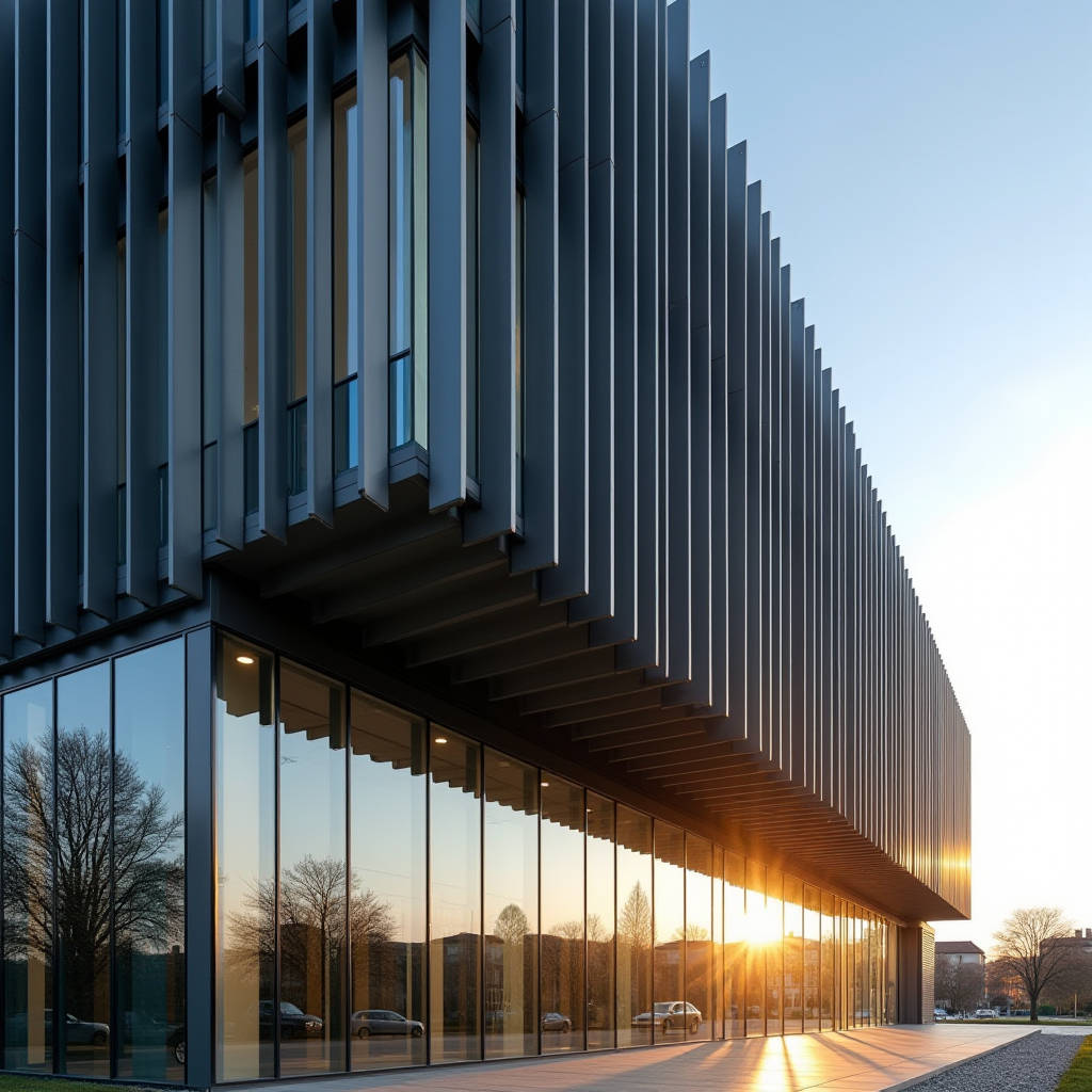
Designing a functional aluminium fins facade requires moving beyond aesthetic rendering to address the critical structural physics governing exterior protrusions. Unlike flat curtain walls, these projecting elements act as cantilevers subject to complex torsional forces and amplified wind pressures. Engineers must calculate specific moment loads based on fin depth, aspect ratio, and local wind codes to prevent fatigue failure or excessive deflection. Selecting the correct solid aluminium grade and temper is non-negotiable for maintaining dimensional stability under cyclic loading. This technical overview examines the engineering parameters necessary to specify and fabricate aluminium fins facade components that meet rigorous safety standards while delivering intended solar shading performance without compromising long-term structural integrity or coating adhesion in harsh environments.
Wind Load Dynamics on Projecting Fin Elements
The primary engineering challenge for any aluminium fins facade system lies in accurately determining wind loads. Standard building codes typically provide pressure coefficients for flat surfaces, but projecting fins experience different aerodynamic behaviors. The geometry creates localized turbulence and suction effects that can exceed standard face pressures by significant margins. When wind strikes a vertical fin at an oblique angle, it generates both drag and lift forces. These combined vectors create a bending moment at the connection point that dictates the required section modulus of the aluminium profile or fabricated box section.
Calculating these forces requires adherence to recognized standards such as ASCE 7-22 or Eurocode EN 1991-1-4. These documents provide methodologies for determining external pressure coefficients for appendages and projections. However, generic coefficients often serve only as starting points. For complex parametric designs where fin angles vary across the elevation, computational fluid dynamics (CFD) modeling or physical wind tunnel testing becomes necessary to validate peak suctions. Relying solely on simplified static calculations can lead to under-designed connections that fail during extreme weather events. The design wind pressure must be factored with appropriate safety margins, typically 1.5 to 2.0 depending on the limit state being checked.
Gust effect factors play a crucial role in fin design due to their relatively low mass and high natural frequency compared to the main building structure. Lightweight solid aluminium panels respond dynamically to turbulent wind eddies. If the natural frequency of the fin assembly falls within the energy-containing range of the wind spectrum, resonant amplification can occur. Damping characteristics of aluminium are inherently low, meaning the system relies heavily on connection stiffness and friction to dissipate energy. Engineers must verify that serviceability deflection limits are met to prevent visual distortion or glass damage in adjacent glazing systems. A common serviceability limit for cantilevered fins is span/180 or a fixed maximum tip displacement, whichever is more stringent.
Material Selection and Alloy Specifications
Performance of an aluminium fins facade depends directly on the metallurgical properties of the base metal. While many architectural metals are marketed generically, specific alloy tempers offer distinct advantages for structural applications. Solid aluminium cladding used for fins should generally conform to ASTM B209 or EN 485 specifications. The choice between 3003-H14, 5005-H14, and 6061-T6 involves trade-offs between formability, strength, and corrosion resistance.
For folded box fins or simple brake-formed shapes, 3003-H14 provides excellent workability and adequate strength for moderate spans. Its manganese content offers good corrosion resistance and weldability. However, as fin depths increase beyond 300mm or unsupported spans exceed 1.5 meters, the yield strength of 3003 may become insufficient to resist wind-induced bending without excessive thickness. In these scenarios, 5005-H14 offers approximately 20% higher yield strength while maintaining similar forming characteristics and anodizing quality. For extruded fins or heavy-duty fabricated assemblies requiring welded structural connections, 6061-T6 is the industry benchmark. Its magnesium-silicon composition allows heat treatment to achieve yield strengths exceeding 240 MPa, enabling thinner sections and longer spans.
| Alloy & Temper | Yield Strength (MPa) | Tensile Strength (MPa) | Elongation (%) | Best Application | Fabrication Notes |
|---|---|---|---|---|---|
| 3003-H14 | 145 | 150 | 10 | Shallow folded fins, decorative screens | Excellent formability, limited structural span |
| 5005-H14 | 170 | 180 | 12 | Medium-depth fins, anodized finishes | Balanced strength and formability, consistent color |
| 6061-T6 | 240 | 290 | 10 | Structural fins, welded assemblies, long spans | Heat treatable, superior strength, requires post-weld aging |
| 5754-H22 | 190 | 220 | 11 | Marine environments, high corrosion resistance | Superior salt spray resistance, moderate strength |
Thickness selection must account for both structural requirements and fabrication constraints. While 2.0mm sheet may satisfy stress calculations for small fins, practical considerations often dictate minimum 2.5mm or 3.0mm thickness. Thinner gauges are prone to oil-canning and thermal buckling when exposed to direct solar radiation. Solid aluminium expands significantly with temperature changes; a 3-meter fin can expand nearly 5mm over a 40°C temperature differential. Adequate thickness provides the rigidity needed to resist this thermal movement without visible waviness. Suppliers like Futeng® typically recommend 3.0mm as the baseline for exterior structural fins to ensure flatness tolerance remains within acceptable architectural limits after installation.
Connection Design and Structural Interface
The weakest link in most aluminium fins facade failures is not the fin itself but the connection to the primary structure. Cantilevered moments generate substantial shear and tension forces at the anchor points. Connection design must accommodate these forces while allowing for thermal expansion and construction tolerances. Fixed-fixed connections are rarely appropriate for exterior aluminium elements. Instead, engineers should employ slotted holes or sliding brackets at one end to permit longitudinal movement. Restraining thermal expansion induces internal stresses that can distort the fin or overload fasteners.
Stainless steel hardware is mandatory for all structural connections involving aluminium. Direct contact between aluminium and carbon steel causes galvanic corrosion that compromises joint integrity within years. Isolation washers made from EPDM or nylon should separate dissimilar metals even when using stainless fasteners to prevent crevice corrosion. Fastener sizing must consider pull-out strength from the substrate, which is often concrete or steel framing. Anchor embedment depth and edge distances must comply with manufacturer certifications and relevant code provisions. For retrofit projects where substrate condition is uncertain, in-situ pull testing validates design assumptions before full-scale installation proceeds.
Bracket spacing optimization balances material cost against installation labor. Closer spacing reduces required fin thickness and connection size but increases part count and field time. Wider spacing demands heavier sections but accelerates installation. Value engineering exercises should evaluate total installed cost rather than unit material price alone. Parametric modeling tools enable rapid iteration of spacing configurations to identify optimal solutions for specific project geometries. Standardizing bracket types across varying fin lengths simplifies procurement and reduces fabrication errors. Modular sub-assemblies that can be pre-fabricated off-site improve quality control and reduce weather-dependent field work.
Coating Durability and Environmental Performance
Surface finish selection for aluminium fins facade systems must address both UV degradation and mechanical abrasion. Fins receive more intense solar exposure than vertical wall panels due to their orientation and lack of self-shading. PVDF (polyvinylidene fluoride) coatings meeting AAMA 2605 specifications represent the performance standard for exterior architectural aluminium. These fluoropolymer systems retain color and gloss significantly longer than polyester alternatives. Minimum film thickness of 25 microns on the exposed surface ensures adequate barrier protection. Multi-coat systems with primer enhance adhesion and corrosion resistance, particularly in coastal or industrial atmospheres.
Anodizing offers an alternative integral finish that eliminates organic coating delamination risks. Class I anodic coatings per AAMA 611 provide exceptional hardness and UV stability suitable for high-traffic or abrasive environments. However, anodizing color consistency varies with alloy composition and batch processing. Specifying tight color range tolerances and requiring mockup approvals prevents aesthetic disputes. Pre-anodized sheet stock improves consistency compared to post-fabrication anodizing but limits geometric complexity. For projects requiring specific metallic appearances, metallic flake PVDF coatings demand careful application controls to avoid mottling or directional variation. Factory-applied coatings consistently outperform field-applied alternatives in durability and uniformity.
Maintenance access influences both coating selection and detailing. Fins positioned above accessible levels may never receive cleaning, making dirt retention and chalk resistance critical performance criteria. Self-cleaning coating technologies incorporating hydrophilic additives show promise but require validation through long-term exposure testing. Detail design should minimize water traps and debris accumulation points that accelerate coating breakdown. Drip edges and sealed joints prevent moisture ingress behind the finish. Specifying accelerated weathering test data from coating suppliers verifies claimed performance matches project-specific environmental conditions. References to AAMA standards provide objective benchmarks for comparing competing coating systems.
Fabrication Tolerances and Installation Sequencing
Precision fabrication distinguishes successful aluminium fins facade installations from problematic ones. Tolerance accumulation across multiple components can result in misaligned fins that compromise both aesthetics and performance. Industry standards such as those published by the AWCI provide guidance on acceptable deviations. Typical straightness tolerances for extruded or fabricated fins are L/1000 or 3mm maximum, whichever is less. Twist tolerances are equally important for maintaining consistent shadow lines. Fabricators must implement jigs and fixtures to maintain dimensional accuracy during welding and assembly. Post-weld straightening corrects distortion but introduces residual stresses that may relax over time.
Installation sequencing affects final alignment quality. Establishing primary reference planes before fixing individual fins ensures overall geometric coherence. Adjustable bracket systems compensate for substrate irregularities without forcing fins into distorted positions. Temporary bracing maintains alignment until permanent connections are fully tightened. Field cutting or drilling of coated aluminium requires immediate touch-up treatment to prevent corrosion initiation. Protection measures during construction prevent damage from adjacent trades. Packaging and handling protocols minimize surface scratches that become visible under raking light conditions.
Quality assurance protocols should include sample testing of fabricated assemblies. Load testing representative samples validates engineering calculations and fabrication quality. Coating adhesion tests confirm proper pretreatment and cure. Dimensional surveys verify compliance with specified tolerances before shipment. Documentation packages including mill certificates, coating warranties, and installation manuals support future maintenance and liability management. Engaging fabricators with demonstrated experience in architectural aluminium systems reduces risk of costly rework. Early involvement of fabrication specialists during design development identifies constructability issues before they become change orders.
Thermal Bridging and Energy Considerations
While aluminium fins facade elements primarily serve solar shading functions, their thermal interaction with the building envelope warrants attention. Metal penetrations through insulated walls create thermal bridges that increase heat transfer and condensation risk. Thermal break pads inserted between fin brackets and structural backing reduce conductive losses. Materials such as reinforced polyamide or fiberglass-reinforced plastic provide adequate compressive strength while limiting heat flow. Condensation analysis determines whether additional vapor barriers or insulation continuity measures are necessary at penetration points.
Solar shading effectiveness depends on fin geometry relative to sun path. Horizontal fins optimize north-south facades in northern latitudes, while vertical fins better control east-west exposures. Integrated energy modeling quantifies cooling load reductions attributable to specific fin configurations. Daylight autonomy studies balance glare control against artificial lighting energy penalties. Reflective finishes redirect daylight deeper into interior spaces but may cause unwanted glare for neighboring buildings. Matte or low-gloss finishes minimize specular reflection while maintaining solar reflectance index values sufficient to reduce urban heat island effects. Coordination between facade engineers and energy consultants ensures fin design supports overall sustainability targets without unintended consequences.
Life cycle assessment increasingly influences material specification decisions. Aluminium's recyclability and durability contribute favorably to environmental product declarations. Sourcing primary aluminium from smelters using renewable energy reduces embodied carbon significantly. Regional manufacturing minimizes transportation emissions. End-of-life recovery infrastructure exists globally for architectural aluminium. Specifying recycled content percentages supports circular economy objectives without compromising performance. Documentation of material provenance and processing history satisfies green building certification requirements. Balancing initial cost against long-term environmental and operational benefits justifies premium material selections where lifecycle value demonstrates clear advantage.