Aluminium External Wall Cladding Rainscreen Drainage And Wind Load Design
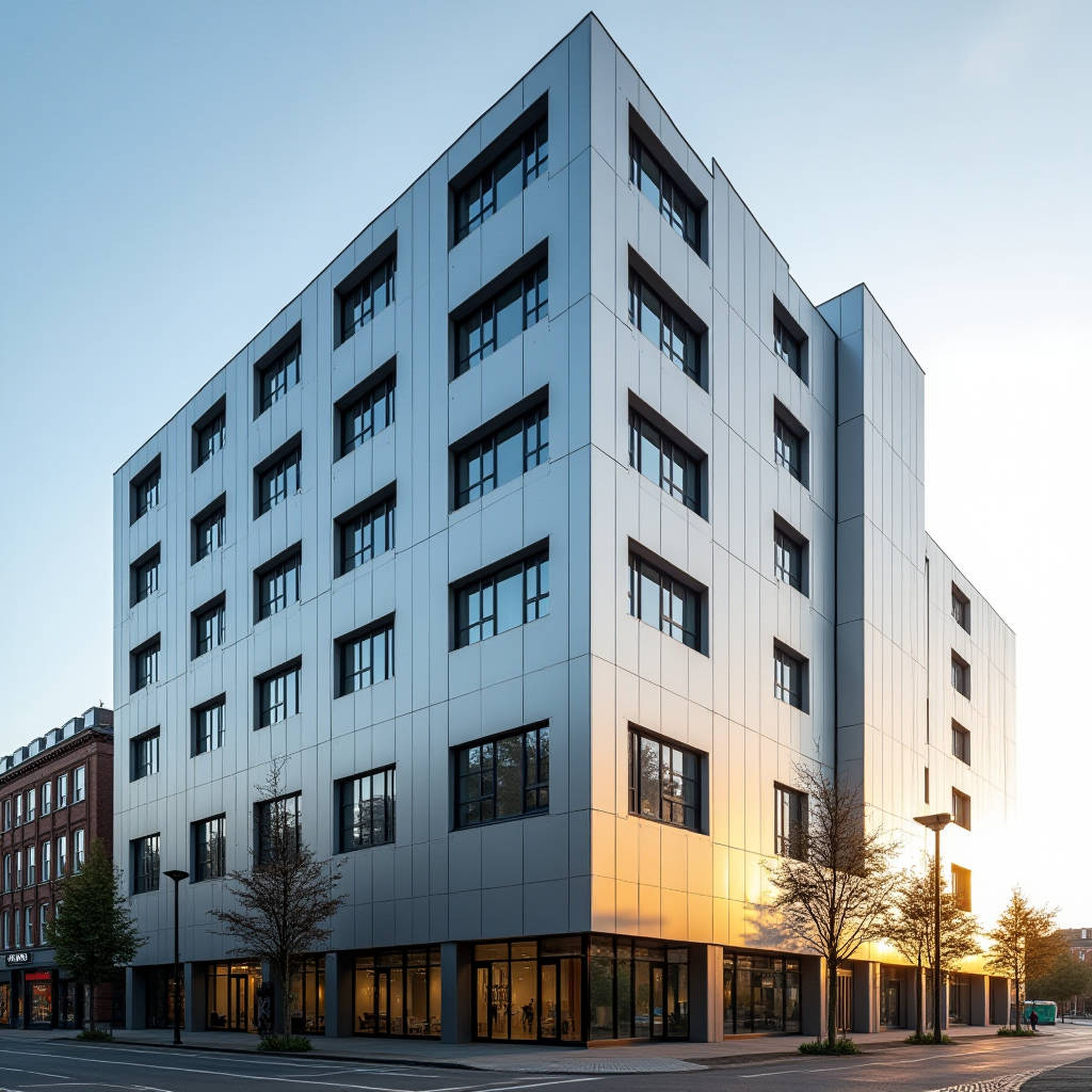
Specifying aluminium external wall cladding for commercial facades demands rigorous attention to rainscreen cavity dynamics and structural wind load resistance rather than surface aesthetics alone. Solid aluminium panels function as the primary weather shield in a drained and back-ventilated system where performance relies entirely on pressure equalization principles and adequate drainage capacity. Failure to calculate correct cavity depth or bracket spacing frequently leads to water ingress, panel deformation under negative suction loads, or accelerated coating degradation due to trapped moisture. This technical overview addresses the critical engineering parameters governing 2.0mm to 3.0mm solid aluminium sheet installations, focusing on compliance with international testing standards and practical site execution strategies that ensure long-term facade integrity across diverse climatic zones.
Rainscreen Cavity Depth and Drainage Capacity
The fundamental performance mechanism of any aluminium external wall cladding assembly is the drained and back-ventilated rainscreen principle. The outer solid aluminium panel serves as a rain deflector, not an absolute waterproof barrier. Water that penetrates the open joints must be safely managed within the cavity and directed out through weep vents without contacting the air barrier or insulation layer behind. Industry best practice, supported by ASTM E330 test protocols, establishes that minimum cavity depth directly influences both drainage efficiency and ventilation rates.
For standard flat solid aluminium panels ranging from 2.0mm to 3.0mm thickness, a minimum unobstructed cavity depth of 25mm is generally required for low-rise applications under 15 meters. However, high-rise projects or buildings in severe wind-driven rain zones typically demand cavities between 40mm and 75mm. This increased depth serves two purposes: it provides sufficient volume for water droplets to lose momentum before reaching the secondary weather barrier, and it creates adequate airflow to promote drying. Narrower cavities increase the risk of capillary action drawing water across to the substrate during extreme weather events.
Drainage area calculations must account for the specific joint configuration of the aluminium external wall cladding system. Open horizontal joints typically range from 10mm to 20mm depending on panel module size and expected wind pressures. Weep vent spacing at the base of each floor level should never exceed 600mm horizontally, with individual vent areas sized to handle calculated peak rainfall intensities for the project location. Blocked or undersized weeps represent one of the most common failure points in metal facade systems, leading to hydrostatic pressure buildup that can force water past flashings and into building interiors.
Ventilation Requirements for Moisture Management
Adequate cross-ventilation within the rainscreen cavity prevents condensation accumulation and accelerates drying cycles after rain exposure. The ventilation rate depends on cavity depth, building height, and local climate humidity levels. For aluminium external wall cladding installed in humid coastal environments, continuous vertical ventilation channels combined with horizontal airflow paths at each floor slab provide optimal moisture evacuation. Stagnant air pockets within poorly designed cavities create microclimates that accelerate corrosion of steel subframe components and degrade sealant performance at perimeter flashings.
Computational fluid dynamics modeling has become increasingly valuable for complex facade geometries where natural stack effect ventilation may be compromised by architectural features such as deep reveals, projecting fins, or irregular panel layouts. These models help identify zones of insufficient airflow that require supplementary mechanical ventilation or modified cavity detailing to maintain long-term durability of the aluminium external wall cladding assembly.
Wind Load Engineering and Structural Fixing
Solid aluminium panels possess inherent stiffness advantages over composite alternatives, yet they remain susceptible to permanent deformation if support spacing exceeds material yield limits under design wind loads. Unlike flexible membranes or thin-gauge metal sheets, 2.5mm and 3.0mm solid aluminium external wall cladding can span greater distances between fixings, but this capability must be verified through project-specific structural calculations rather than generic manufacturer tables.
Wind load assessment for facade cladding follows localized pressure coefficients defined in standards such as ASCE 7-22 or EN 1991-1-4. Corner zones, roof edges, and parapet caps experience significantly higher suction forces than field areas, often requiring reduced bracket spacing or thicker panel gauges in these critical regions. A uniform fixing grid applied across the entire facade ignores these localized pressure variations and risks catastrophic panel detachment during storm events. Engineers must map pressure zones accurately and specify corresponding reinforcement strategies for each zone.
Bracket and rail systems supporting aluminium external wall cladding must accommodate differential thermal movement between the aluminium panels and the primary building structure. Aluminium expands approximately twice as much as steel or concrete per degree of temperature change. Fixed-point connections should be limited to one location per panel or panel group, with all other fixings utilizing slotted holes or sliding clips that permit unrestricted thermal expansion. Restrained thermal movement generates internal stresses that manifest as oil-canning, buckling, or fastener fatigue over the service life of the facade.
Panel Stiffness and Span Limitations
The relationship between panel thickness, unsupported span, and allowable deflection governs the economic viability of solid aluminium external wall cladding specifications. Deflection limits typically follow L/180 or L/240 criteria under service loads, with stricter limits applied where adjacent panels share visible joints. Exceeding these thresholds produces visually unacceptable waviness even when structural safety margins remain intact.
| Panel Thickness (mm) | Max Span @ 1.5 kPa (mm) | Max Span @ 3.0 kPa (mm) | Weight (kg/m²) | Typical Application Zone |
|---|---|---|---|---|
| 2.0 | 450 | 320 | 5.4 | Low-rise soffits, interior accents |
| 2.5 | 600 | 420 | 6.8 | Standard wall fields, mid-rise |
| 3.0 | 750 | 530 | 8.1 | High-wind corners, tall buildings |
| 4.0 | 950 | 680 | 10.8 | Parapets, extreme exposure zones |
Data presented assumes simply-supported boundary conditions with PVDF-coated 5052-H32 marine-grade aluminium alloy. Actual permissible spans vary based on specific alloy temper, coating system weight, and project deflection criteria. Suppliers like Futeng® routinely provide certified span tables derived from third-party laboratory testing to AAMA 508 or equivalent standards, which should always supersede theoretical calculations for final specification approval. Field verification through mock-up testing remains advisable for projects with unusual geometry or exposure conditions.
Coating Durability and Material Specification
The longevity of aluminium external wall cladding depends fundamentally on the coating system's resistance to ultraviolet radiation, chemical pollutants, and mechanical abrasion. Fluoropolymer coatings based on PVDF resin chemistry dominate premium facade applications due to their proven 20+ year color retention and chalk resistance characteristics. Polyester powder coatings offer cost savings for sheltered or short-service-life projects but degrade noticeably faster in direct UV exposure.
Specification documents should reference ISO 12944 corrosion categories appropriate to the project environment. Marine coastal sites typically require C4 or C5-M classification with minimum total dry film thickness of 80 microns including primer and topcoat layers. Industrial urban environments with elevated sulfur dioxide concentrations similarly demand enhanced protection systems beyond standard architectural finishes. Pre-treatment processes including chromate-free conversion coatings provide essential adhesion promotion and undercut corrosion resistance that bare aluminium cannot achieve independently.
Color selection impacts thermal performance and coating lifespan. Dark pigments absorb significantly more solar energy than light colors, raising panel surface temperatures by 20°C to 30°C above ambient in direct sunlight. Elevated temperatures accelerate coating degradation mechanisms and increase thermal movement demands on fixing systems. Some manufacturers now offer cool pigment technologies that reflect near-infrared radiation while maintaining desired visible color appearance, reducing thermal stress on aluminium external wall cladding assemblies in hot climates.
Alloy Selection for Formability and Strength
Marine-grade 5052-H32 aluminium alloy represents the industry benchmark for exterior cladding due to its balanced combination of formability, weldability, and corrosion resistance. Alternative alloys such as 3003-H14 offer lower cost and excellent formability for simple curved profiles but sacrifice strength and salt spray resistance. High-strength 6061-T6 alloy enables longer spans and thinner gauges but exhibits reduced formability and requires specialized welding procedures that complicate fabrication of complex shapes.
Material certification documentation should verify alloy designation, temper condition, and mill source traceability for every batch of aluminium external wall cladding supplied to site. Substitution of non-specified alloys without engineer approval introduces unpredictable performance variables that may not surface until years after installation. Reputable fabricators maintain comprehensive material traceability records and welcome third-party audit requests from quality-conscious specifiers.
Installation Tolerances and Quality Verification
Precision during installation determines whether engineered aluminium external wall cladding systems perform as designed or develop chronic issues requiring costly remediation. Panel alignment tolerances typically specify ±2mm maximum deviation from true plane across any 3-meter measurement length, with cumulative drift limited to ±5mm over full facade height. Achieving these tolerances demands disciplined subframe adjustment procedures and systematic verification using laser survey equipment rather than visual estimation.
Fastener torque control prevents both under-tightening that permits rattling and over-tightening that distorts panel faces or strips threads in aluminium extrusions. Calibrated torque wrenches or electronic screwdrivers with preset limits should be mandatory site tools. Self-drilling fasteners used for direct-fix applications require particular attention to drill point geometry and thread pitch matching the substrate material; mismatched fasteners generate excessive heat during installation that damages protective coatings and compromises withdrawal resistance.
Sealant application at perimeter flashings, penetration collars, and expansion joints must follow manufacturer-approved priming and tooling procedures. Incompatible sealants chemically attack PVDF coatings or fail to adhere to mill-finish aluminium substrates. Joint width-to-depth ratios, backer rod compression, and wet-film thickness all influence long-term sealant performance. Site quality assurance programs should include regular adhesion testing and destructive sampling of completed sealant work to verify compliance before enclosing critical interfaces.
Mock-Up Testing and Performance Validation
Project-specific mock-ups serve multiple validation functions beyond aesthetic approval. Water spray testing per ASTM E1105 confirms that fabricated panel assemblies achieve intended watertightness under simulated wind-driven rain conditions. Structural load testing verifies that actual installed fixings and brackets meet calculated capacity requirements without excessive deflection or permanent set. Thermal imaging during mock-up evaluation identifies unintended thermal bridges or insulation gaps that compromise energy performance.
Documenting mock-up construction sequences, adjustment procedures, and inspection checkpoints creates a reproducible quality baseline for full-scale production. Deviations from approved mock-up methods during mass installation frequently introduce defects absent from the validated prototype. Continuous supervision by personnel who participated in mock-up development ensures knowledge transfer from test phase to production phase maintains consistent aluminium external wall cladding performance across the entire building envelope.
Successful aluminium external wall cladding projects result from systematic integration of rainscreen science, structural engineering, materials specification, and installation discipline. Each parameter discussed herein interacts with others; optimizing one aspect while neglecting adjacent requirements produces suboptimal outcomes regardless of individual component quality. Facade consultants, structural engineers, coating suppliers, and installers must collaborate throughout design and construction phases to resolve interface details before fabrication begins. Post-occupancy performance monitoring during the first two years of service provides valuable feedback for refining future specifications and identifying maintenance needs before minor issues escalate into major failures.