Solid Facade Aluminum Panels Engineering Guide for Wind Load Flatness and Coating Verification
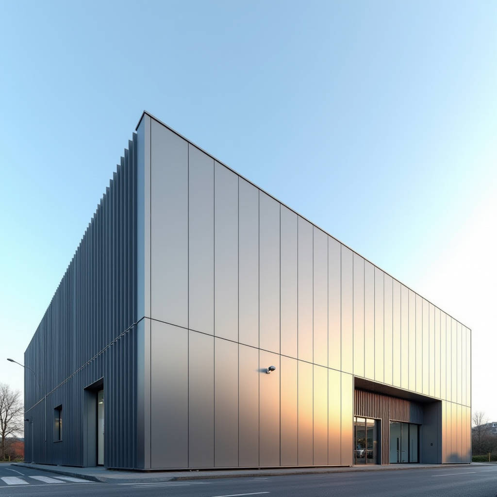
When a facade aluminum specification moves from the architect's sketch to the fabrication shop, the real engineering begins. Solid aluminium cladding panels are not interchangeable with thinner composite systems, and the difference shows up in wind load resistance, flatness tolerance, and long-term coating performance. For contractors and procurement managers who must justify every material decision, the critical question is how to specify, fabricate, and install solid panels so that the building envelope performs for decades without costly callbacks. This article walks through the load paths, panel thickness logic, and coating verification steps that separate a durable facade aluminum project from a warranty headache, with practical numbers you can take straight into your next tender.
Why Solid Panels Carry Different Engineering Assumptions
Solid aluminium cladding panels are milled from a single sheet of metal, typically 2.0 mm, 2.5 mm, or 3.0 mm thick, rather than a thin aluminium skin bonded to a polyethylene or mineral core. That single-layer construction changes how the panel resists wind suction, how it transfers load to the substructure, and how it behaves under thermal movement. The stiffness of a solid panel comes almost entirely from its thickness and the geometry of its returns and stiffeners, not from a composite core.
For a 2.0 mm solid panel, the flexural stiffness is roughly proportional to the cube of the thickness. Increasing from 2.0 mm to 3.0 mm raises bending stiffness by a factor of about 3.4, which is why high-rise projects with large panel modules routinely move to 3.0 mm. The substructure spacing, the panel width, and the wind zone all interact here. A common design rule is to keep the unsupported span of a 2.0 mm panel under 800 mm, while a 3.0 mm panel can comfortably span 1000 mm to 1200 mm with the same deflection limit.
This is not a cosmetic difference. Deflection limits for cladding are typically set at L/180 for wind load, and exceeding that limit causes oil-canning, waviness, and eventual fatigue at the fixing points. Contractors who substitute a thinner panel to save cost often discover the flatness problem only after installation, when the building is already scaffolded and the rectification cost exceeds the original saving.
Load Paths and Substructure Design
The facade aluminum panel does not carry wind load on its own. The load travels from the panel face, through the fixing brackets, into the aluminium or steel subframe, and finally into the structural slab or concrete wall. Each link in that chain has a rated capacity, and the weakest link sets the project limit.
For a typical 1500 mm x 3000 mm solid panel in a 45 m/s wind zone, the design wind pressure can reach 2.5 kPa to 3.5 kPa on the face. That translates to a total lateral force of roughly 11 kN to 16 kN per panel, which must be distributed across the fixing points. With four corner brackets plus intermediate supports, each bracket carries a portion of that load, and the bracket-to-subframe connection must be verified against both pull-out and shear.
Thermal movement is the second load that kills poorly detailed solid panels. Aluminium expands at roughly 23 x 10^-6 per degree Celsius. A 3000 mm long panel experiencing a 60-degree temperature swing moves about 4.1 mm. If the fixing system locks the panel rigidly, that movement converts directly into stress and distortion. The correct approach uses slotted holes and a sliding connection at one end, allowing the panel to breathe without transferring stress into the substructure.
Coating Systems and Verification
The coating is the first line of defence against corrosion, UV degradation, and chalking. For exterior solid aluminium cladding, the industry standard is a two-coat or three-coat PVDF (polyvinylidene fluoride) system with a total dry film thickness of at least 25 microns for two-coat and 35 microns for three-coat. The PVDF resin content should be at least 70 percent, which is the threshold that gives the coating its long-term weatherability.
Verification is where many projects go wrong. A certificate from the coil supplier is not enough, because the coating is applied after the panel is formed, and the film thickness can vary around bends and returns. A practical specification requires the fabricator to measure dry film thickness on the finished panel at multiple points, including at the edges and near the returns, and to record the readings in a QC report. The ASTM D3363 pencil hardness test and the MEK rub test are quick field checks that confirm the coating has been properly cured.
For coastal projects, the salt-spray performance matters more than the gloss. A solid panel with a quality PVDF finish will pass 4000 hours of ASTM B117 salt spray without significant corrosion at a scribe mark. Cheaper polyester coatings fail well before that threshold, which is why the coating specification should always be written into the tender documents rather than left to the fabricator's discretion.
Flatness, Tolerances, and Oil-Canning Control
Flatness is the single most visible quality attribute of a solid panel facade, and it is also the hardest to control. Oil-canning, the visible waviness that appears in large flat areas, is caused by differential stress in the metal, often introduced during the forming process or by uneven thermal expansion after installation.
Several fabrication techniques reduce oil-canning. The most effective is to add stiffening ribs or a back-up frame behind large flat areas, which breaks the panel into smaller unsupported spans. Another approach is to introduce a subtle crown or curvature into the panel face, which pre-stresses the metal and prevents the flapping motion that causes visible distortion. The panel tolerance per ASTM standards allows a flatness deviation of roughly 1.5 mm per 300 mm of width, but in practice a well-made panel will hold tighter than that.
For procurement, the tolerance specification should be written as a measurable acceptance criterion. A common clause is that no panel shall show visible distortion when viewed from a distance of 3 metres under diffuse daylight, and that any deviation exceeding 2 mm over a 600 mm span triggers rejection. This is a contractable, testable requirement, not a vague aesthetic preference.
Fabrication and Installation Sequence
The quality of a facade aluminum project is decided as much on site as in the factory. The installation sequence matters because the panel system must accommodate the building's actual geometry, which never matches the drawings perfectly.
A reliable sequence starts with a full 3D survey of the structural openings before any fabrication. The survey data is used to set the subframe positions, and the panel dimensions are derived from those field measurements rather than from the architectural drawings alone. This reduces the number of out-of-tolerance panels and the associated rework.
On site, the subframe must be installed plumb and level within 3 mm over a 3 m run, and the panel fixing points must be checked for alignment before the panels are hung. Panels are typically installed from the bottom up, with the lower panel acting as a support ledge for the one above. The sealant joints, usually 10 mm to 15 mm wide, must be clean and free of oil before the silicone is applied, and the backer rod must be sized correctly to control the joint depth.
Cost and Performance Comparison of Common Panel Setups
The table below compares three common solid panel configurations across the factors that matter most to a contractor or procurement manager. The figures are indicative for a mid-rise commercial project in a moderate wind zone and should be adjusted for local conditions.
| Parameter | 2.0 mm Panel, 600 mm Span | 2.5 mm Panel, 800 mm Span | 3.0 mm Panel, 1000 mm Span |
|---|---|---|---|
| Relative material cost per m2 | 1.00 | 1.25 | 1.50 |
| Subframe weight per m2 | Higher (denser fixing) | Moderate | Lower (wider span) |
| Max unsupported span | 800 mm | 1000 mm | 1200 mm |
| Oil-canning risk on large flats | High | Moderate | Low |
| Typical use case | Low-rise, small modules | Mid-rise, standard modules | High-rise, large modules |
| Installed cost per m2 (relative) | 1.00 | 1.15 | 1.30 |
The installed cost gap is smaller than the material gap, because the thicker panel saves on subframe density and installation labour. For a project with large panel modules or high wind loads, the 3.0 mm option often delivers the best total installed cost despite the higher material price.
Standards and Reference Documents
Every specification should reference the relevant standards so that the acceptance criteria are unambiguous. The following documents are the most useful for solid aluminium cladding work:
- ASTM B209 for aluminium sheet and plate tolerances and mechanical properties.
- ASTM D3363 for the pencil hardness test on the coating.
- ASTM B117 for the salt spray corrosion test.
- AAMA 2605 for the highest-performance exterior coating specification, which is the right benchmark for coastal and high-exposure projects.
- ISO 12944 for corrosion protection of steel structures, useful when the substructure is galvanized steel.
Writing these references into the tender documents gives the contractor a clear, enforceable quality baseline. Without them, disputes over coating thickness, flatness, and corrosion resistance become subjective arguments that are expensive to resolve.
Practical Advice for Procurement and Engineering Teams
For a solid aluminium cladding project, the engineering effort should be front-loaded. Confirm the wind zone and design pressure early, fix the panel module and thickness before the substructure is detailed, and write the coating and tolerance requirements into the contract. A fabricator with proven solid panel capability, such as Futeng®, can provide the QC documentation and test certificates that let a procurement team verify compliance without relying on trust alone.
On the cost side, compare total installed cost rather than material price per square metre. The thicker panel that allows wider subframe spacing often wins on the full installation budget. On the quality side, insist on a pre-production sample panel that is finished and coated exactly as the production panels will be, and use it as the visual and dimensional reference for the whole project.
Finally, plan for thermal movement in the fixing design and verify the coating on the finished panel, not just on the coil. These two details are where most facade aluminum failures originate, and both are fully controllable with the right specification and inspection regime. A solid panel envelope that is engineered for its real load and movement conditions will perform quietly for decades, which is exactly what a building owner and a contractor both want.