Engineering Perforated Facade Aluminium Panels for Solar Control and Ventilation
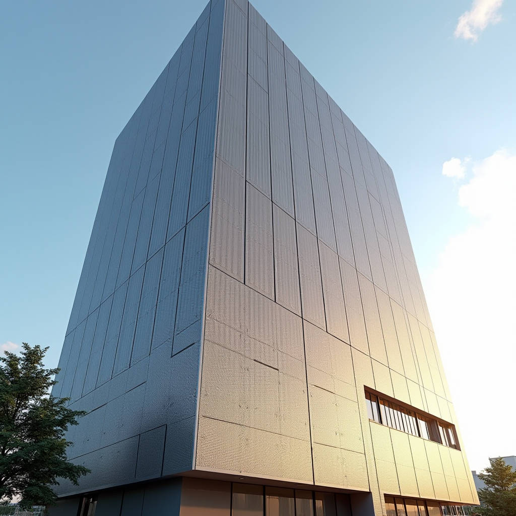
Perforated facade aluminium panels have moved from a decorative afterthought to a central tool in modern building-envelope engineering. Architects and facade contractors increasingly specify them not simply for their visual texture, but for the measurable way they manage solar gain, daylight, and natural ventilation across a curtain wall. The engineering question is no longer whether to use perforated facade aluminium panels, but how to specify the perforation geometry, open area ratio, and backing layers so that the panel performs predictably under wind load, acoustic requirements, and long-term weathering. This article walks through the calculation logic, the coating and alloy decisions, and the installation details that separate a facade that performs for thirty years from one that fails in five.
Why Perforation Changes the Engineering Rules
A solid sheet of aluminium behaves like a simple membrane under wind pressure. Perforate it, and you introduce stress concentrations around every hole, a reduced effective stiffness, and a completely different airflow behaviour across the building envelope. The open area ratio, typically expressed as a percentage of the panel face, drives most of the downstream decisions. At 10% open area the panel still reads as a largely solid surface; at 40% it becomes a true sun-screen and loses most of its rain-screen function. Between those extremes lies the practical design window for most commercial facades.
The structural consequence is immediate. A 3.0 mm solid aluminium panel with a 600 mm by 1200 mm unsupported span can carry a wind load that a similar panel at 30% open area cannot match without a denser subframe. The perforation pattern also dictates the minimum edge distance from the hole to the panel perimeter, which in turn sets the practical limits on panel width and the location of fixing points. Contractors who ignore these constraints end up with oil-canning, edge curl, or fatigue cracking around the perforations after a few years of thermal cycling.
Core Specification Parameters
Every perforated facade aluminium panels project should start with a written performance brief that locks down five numbers before any aesthetic discussion begins.
- Open area ratio — the percentage of the panel face removed by holes, typically 15% to 45% for sun-screens.
- Hole diameter and pitch — round holes from 3 mm to 20 mm, with a pitch that keeps the ligament (the material between holes) at least 1.5 times the panel thickness.
- Panel thickness — 2.0 mm, 2.5 mm, or 3.0 mm solid aluminium, never composite.
- Coating system — PVDF (polyvinylidene fluoride) at 70% resin content, applied at a dry film thickness of 25 to 30 microns per coat.
- Backing and cavity — whether a perforated outer skin sits over a solid inner liner, and the depth of the ventilated cavity behind it.
The relationship between hole diameter and panel thickness is the first thing a good fabricator checks. A 3.0 mm panel can accept a 12 mm hole with a comfortable ligament width, while a 2.0 mm panel with the same hole leaves a ligament that is too thin and risks burr formation during punching. Most reputable suppliers, including Futeng®, hold their punching tolerances to within ±0.1 mm on hole diameter and keep the burr height under 0.05 mm on the visible face.
Wind Load and Structural Verification
Perforated panels must be checked for two distinct failure modes: global deflection of the panel between supports, and local stress around the perforations. The effective section modulus of a perforated plate is lower than the equivalent solid sheet, so the deflection calculation must use a reduced stiffness. A practical rule used across the industry is to treat the perforated panel as having an effective thickness of roughly 0.85 to 0.92 times the nominal thickness for open area ratios up to 30%, with the reduction factor falling as the open area rises.
For a typical high-rise application with a design wind pressure of 1.8 kPa, the deflection limit is usually set at L/180 or L/250 depending on the local code. The subframe spacing then becomes the controlling variable. A 2.5 mm panel at 25% open area over a 900 mm span will typically stay within L/250 at 1.8 kPa, but pushing the span to 1200 mm without a heavier frame will exceed the limit. These numbers are not academic; they decide the number of vertical mullions and therefore a meaningful share of the installed cost.
For perforated panels, the structural check is not complete until the local stress at the ligament between adjacent holes is verified against the alloy's fatigue limit under cyclic wind loading.
Design guidance on perforated plate behaviour can be cross-referenced with the general aluminium design rules in the AISC Specification for Structural Aluminum Buildings, and the wind-load derivation itself follows the procedures in ASCE 7. For coating durability, the relevant benchmark is AAMA 2605, which sets the highest performance class for PVDF finishes on architectural aluminium.
Coating and Alloy Selection for Perforated Panels
The perforation process exposes fresh aluminium edges that are more vulnerable to corrosion than the coated face. This makes the choice of alloy and coating more consequential than on a solid panel. The standard architectural alloy is 3003 or 5005, both offering good corrosion resistance and formability. The coating must cover the cut edges, so the edge of every hole needs a minimum PVDF film build, and the fabricator should apply a protective edge treatment or ensure the coating wraps into the hole sufficiently.
The table below compares the three coating classes a specifier will encounter, with the performance levels that matter for a perforated facade.
| Coating Class | Resin System | Dry Film Thickness | UV / Chalk Resistance | Typical Application |
|---|---|---|---|---|
| AAMA 2603 | Polyester | 20–25 microns | Moderate | Interior, short-life projects |
| AAMA 2604 | PVDF (50% resin) | 25 microns | Good | Standard exterior facades |
| AAMA 2605 | PVDF (70% resin) | 25–30 microns per coat | Excellent, 30-year warranty | High-rise, coastal, perforated panels |
For a perforated panel exposed to driving rain and salt, specifiers should push toward AAMA 2605. The higher resin content and film build give the coating the flexibility to bridge the cut edges of the holes without cracking during thermal movement. A 2.5 mm or 3.0 mm panel with a 70% PVDF system is the workhorse specification for perforated sun-screens on commercial towers.
Acoustic and Ventilation Performance
Perforation is not only a visual and shading device. The open area also affects how the facade behaves acoustically and how the cavity behind the panel ventilates. A perforated outer skin over a solid inner liner and an acoustic insulation layer creates a resonant absorber that can be tuned by adjusting the hole diameter, the open area, and the cavity depth. This is a genuine engineering lever for projects near roads or rail lines, where the facade must cut both solar gain and noise.
Ventilation follows a similar logic. The perforated panel allows air to move through the cavity, which helps manage condensation and reduces heat buildup behind the cladding. The cavity depth should be sized to allow adequate airflow, typically 30 mm to 50 mm for a ventilated rainscreen, and the perforation pattern should be continuous enough to avoid dead zones where moisture can stagnate. The combination of a perforated outer skin and a ventilated cavity is one of the most reliable ways to keep the structural wall dry over decades of service.
Installation and Fabrication Details
Fabrication quality determines whether the perforation pattern reads cleanly across a full elevation. The holes must align consistently from panel to panel, and the panel edges must be squared to tight tolerances or the pattern will drift visibly across the facade. Reputable fabricators hold panel flatness to within 1.5 mm per metre and squareness to within 1 mm across the panel diagonal.
On site, the installation sequence matters as much as the panel itself. The subframe must be set level and plumb before the panels go on, and the fixing points must allow for thermal expansion in both directions. A 3.0 mm aluminium panel can move several millimetres across a 1200 mm width through a summer-to-winter temperature swing, so the fixings need slotted holes or spring clips that accommodate that movement without transferring stress into the perforations. Sealing the perimeter of a perforated panel is a common mistake; the whole point of the perforation is to let air through, so the cavity should be designed as a drained and ventilated system rather than a sealed one.
Cost and Lead-Time Considerations
Perforation adds a fabrication step that carries a real cost. The punching or laser-cutting process, the tooling, and the additional quality inspection all add to the per-square-metre price compared with a solid panel. The cost impact scales with the open area ratio and the hole density, so a heavily perforated sun-screen will cost noticeably more than a lightly perforated panel. Lead times also stretch, because perforation is a dedicated production step that cannot be rushed without compromising burr quality.
For a project team weighing perforated against solid facade aluminium panels, the total installed cost should include the denser subframe that perforation often requires, the additional coating edge protection, and the longer fabrication lead time. When these are all accounted for, perforated panels still deliver a strong value case where solar control, daylight, and ventilation are genuine project requirements, because they can replace separate sun-shading devices and reduce the cooling load on the building.
Practical Recommendations
For a facade contractor or architect specifying perforated facade aluminium panels, the sequence that produces a reliable result is straightforward. Lock the open area ratio and hole geometry into the performance brief before any aesthetic review. Verify the structural capacity of the panel and subframe against the site wind load, using a reduced effective stiffness for the perforated plate. Specify a 2.5 mm or 3.0 mm solid aluminium panel with a 70% PVDF coating conforming to AAMA 2605, particularly for coastal or high-rise work. Confirm the fabricator's punching tolerance and burr control, and design the cavity as a drained and ventilated system with fixings that allow thermal movement. A supplier with established fabrication capability, such as Futeng®, can hold these tolerances and back them with consistent coating quality, which removes a large share of the risk from the supply chain.
Perforated panels reward discipline at the specification stage. When the numbers are set early and the fabrication tolerances are enforced, the result is a facade that delivers reliable solar control, natural ventilation, and a distinctive architectural texture for decades. The engineering is not complicated, but it is unforgiving of shortcuts, and the projects that succeed are the ones that treat the perforation pattern as a structural and environmental parameter rather than a purely cosmetic one.