Drilled Aluminium Plate Engineering for Facades: Hole Tolerances, Speeds, and Coating Edge Integrity
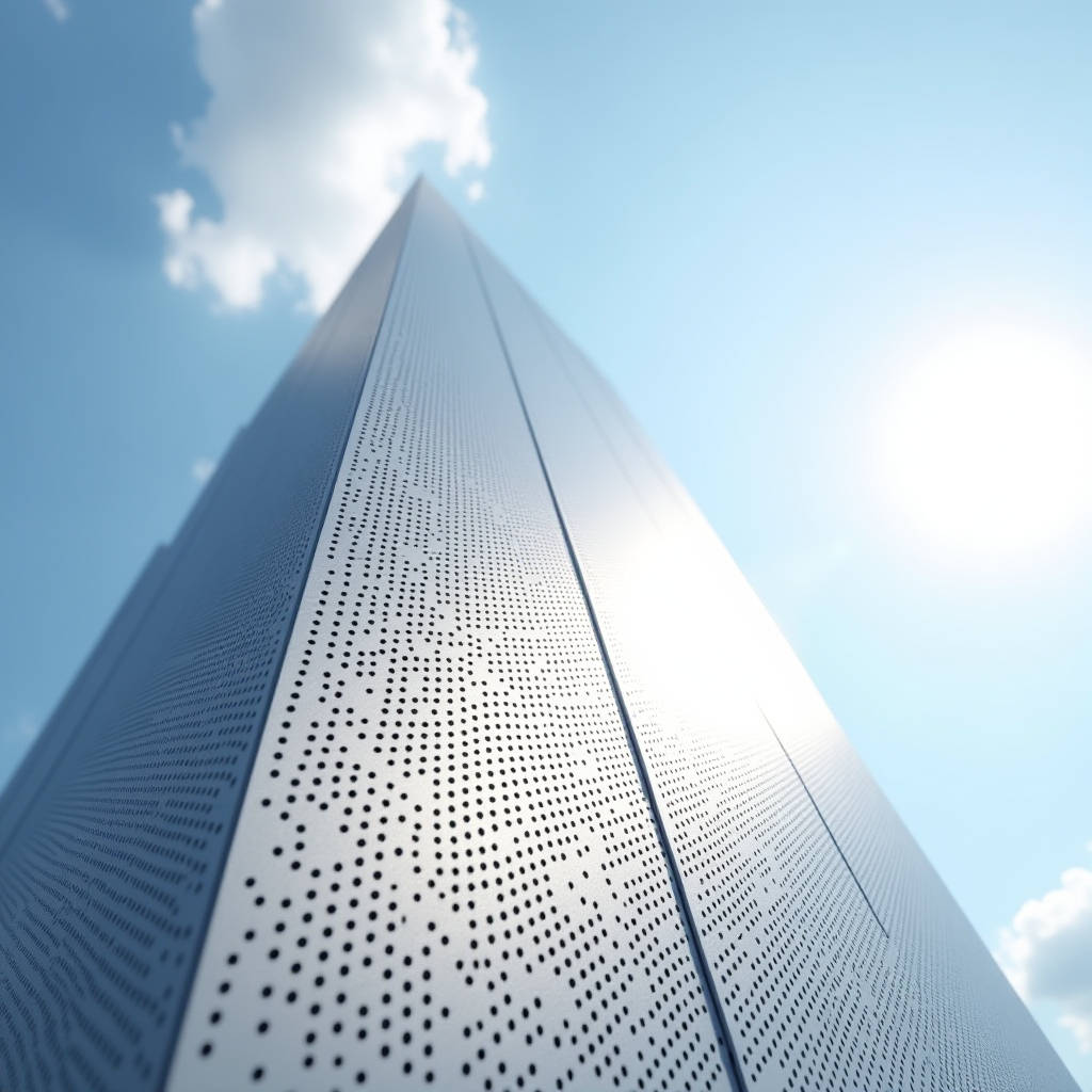
Drilling holes into a solid aluminium cladding plate is one of the most common yet most misunderstood operations in facade fabrication. A drilled aluminium plate that looks acceptable on the bench can fail on site, whether through ragged hole edges that crack under thermal movement, oversized fixings that strip under wind suction, or chips that compromise the PVDF coating. This article focuses on the engineering reality behind drilled aluminium plate for curtain wall and rainscreen systems: how hole geometry, drill bit selection, spindle speed, and plate alloy interact, and how these variables translate into measurable performance on a 2.0 mm, 2.5 mm, or 3.0 mm solid sheet. We will give you the numbers, the tolerances, and the acceptance criteria that a facade contractor actually needs, drawn from ISO and AAMA practice rather than workshop folklore.
Why Hole Quality Matters More Than the Hole Itself
Every fixing, every standoff bracket, every vent slot in a rainscreen system begins as a hole in the panel. When a drilled aluminium plate is produced with a wandering bit or a dull cutting edge, the resulting hole is not round, the exit side carries a burr, and the immediate zone around the hole is work-hardened. On a solid aluminium cladding panel, that work-hardened zone is the first place a stress crack appears when the panel expands and contracts through a daily temperature swing of 40 K or more.
For a 2.5 mm solid sheet, the difference between a clean and a damaged hole is often a matter of 0.1 mm of radial clearance. If the clearance is too tight, the screw binds and the aluminium smears; if it is too loose, the fixing head pulls through under negative wind pressure. The practical outcome is that a drilled aluminium plate must be treated as a precision component, not a quick drilling job.
Alloy Selection Sets the Drilling Window
Not all solid aluminium behaves the same under a drill. The three alloys that dominate facade cladding are 3003, 5052, and 6061, and each has a different machining signature.
- 3003 is the softest and most formable of the three. It drills easily but produces stringy chips and a pronounced exit burr. It is the standard choice for decorative and curved panels where forming matters more than ultimate strength.
- 5052 offers a good balance of strength and corrosion resistance. It machines cleanly with moderate spindle speeds and produces manageable chips. It is the workhorse for most flat and lightly formed cladding.
- 6061-T6 is the strongest and hardest of the three. It requires slower speeds and higher feed pressure, and it is prone to chip welding if lubrication is skipped. It is used where structural fixings must carry higher loads.
For a drilled aluminium plate destined for a high-rise rainscreen, 5052-H32 or 6061-T6 is the safer call. The alloy choice directly changes the recommended spindle speed, the drill bit geometry, and the amount of cutting fluid you will need.
Bit Geometry and Speed: The Numbers That Matter
Standard twist drills are ground for steel, and they perform poorly on aluminium. For a drilled aluminium plate, the drill should have a sharper point angle of 118° to 135°, a polished flute to shed chips, and ideally a split point to stop the bit wandering on the curved or flat panel surface.
Spindle speed is where most shop mistakes happen. Aluminium conducts heat well, so the instinct to spin fast to "cut quicker" is wrong. Excessive speed causes the aluminium to melt and smear onto the cutting edge, which then tears the hole wall instead of cutting it. As a working rule for a solid aluminium cladding panel:
| Hole diameter (mm) | Recommended spindle speed (RPM) | Feed rate guidance | Lubricant |
|---|---|---|---|
| 3.0 – 4.0 | 2,500 – 3,500 | Light, steady pressure | Kerosene or light cutting oil |
| 5.0 – 6.0 | 1,800 – 2,500 | Moderate, no dwell | Light cutting oil |
| 8.0 – 10.0 | 1,200 – 1,800 | Peck drill to clear chips | Cutting fluid |
| 12.0 – 16.0 | 700 – 1,200 | Step drill or annular cutter | Generous fluid |
For diameters above 16 mm, a conventional twist drill is inefficient. An annular cutter or a step drill produces a cleaner hole with far less torque, which matters when the panel is already coated and cannot be reworked.
Backup, Burrs, and the Exit Side
The exit side of a drilled aluminium plate is where quality is lost. As the drill breaks through, the remaining material is thin and unsupported, so it tears upward into a burr. On a coated panel, that burr is a crack initiator and a coating failure point. The standard fix is a backup material: a sacrificial sheet of plywood or a thicker aluminium offcut clamped beneath the panel. This supports the exit side and leaves a clean edge.
When a backup is not possible, the burr must be removed with a deburring tool or a countersink. The acceptance criterion used by most facade contractors is that no burr greater than 0.1 mm may remain on the visible face, and the hole edge on the coated face must show no coating delamination within 2 mm of the hole.
Coating Integrity Around the Hole
A drilled aluminium plate is almost always supplied with a PVDF coating, typically a 25 µm to 30 µm two-coat or three-coat system per AAMA 2605. Drilling after coating is a risk because the cutting action can chip the coating at the hole edge, and the resulting bare aluminium edge is a corrosion entry point.
Two approaches are common in the industry. The first is to drill before coating, so the coating seals the hole edge. The second is to drill after coating and touch up the exposed edge with a compatible PVDF repair paint. For a drilled aluminium plate used in a coastal environment, the pre-coating route is strongly preferred, because a bare machined edge in a marine atmosphere will develop pitting within months.
Where post-coating drilling is unavoidable, the panel should be drilled with a sharp bit at the low end of the speed range, and the hole edge immediately inspected under a 5× magnifier for coating cracks. Any crack wider than 0.05 mm should be treated as a defect.
Vent and Drainage Holes: A Special Case
Rainscreen systems rely on a drilled aluminium plate for pressure equalization and drainage. Vent holes allow the cavity to breathe, and weep holes drain incidental moisture. These holes are small, typically 4 mm to 6 mm, and they are drilled in large numbers across the panel field.
For venting to work, the open area of the vent holes must be balanced against the cavity volume and the wind-driven rain load. A common rule is that the vent open area should be between 0.05% and 0.1% of the panel area. On a 1200 mm × 2400 mm panel, that is between 1,440 mm² and 2,880 mm² of open area, which translates to roughly 90 to 180 holes of 4.5 mm diameter. Getting this balance wrong leads to either a panel that cannot breathe and traps moisture, or one that lets wind-driven rain through the cavity.
Hole Patterns and Structural Load Paths
The layout of holes in a drilled aluminium plate is not cosmetic. Every hole removes material and creates a stress concentration, and the net section between holes carries the full structural load. For a panel fixed with four corner brackets, the load path runs through the corner holes, and the edge distance from the hole centre to the panel edge must be at least two hole diameters to prevent edge tearing.
For a 6 mm fixing hole, that means a minimum edge distance of 12 mm, and for a 10 mm hole, 20 mm. Where holes are arranged in a grid, the pitch between holes should be at least three hole diameters to keep the net section adequate. A drilled aluminium plate that is over-perforated for ventilation can lose enough net section to fail under wind load, so the structural engineer must approve the final hole pattern before fabrication.
Fastener Fit and Pull-Through Resistance
The clearance between the hole and the fixing is a controlled dimension. For a self-tapping screw into a solid aluminium cladding panel, the recommended clearance is 0.5 mm to 1.0 mm on the diameter. A 5 mm screw therefore needs a 5.5 mm to 6.0 mm drilled hole. Too tight a fit binds the screw and smears the aluminium; too loose a fit lets the head pull through the thin panel.
Pull-through resistance is a function of the head size and the panel thickness. For a 2.0 mm panel, a standard countersunk screw head can pull through at a relatively low load, which is why facade fixings for thin panels use larger washers or oversize heads. The practical takeaway is that a drilled aluminium plate's fixing performance is decided at the drilling stage, not at the installation stage.
CNC Drilling: When Volume Justifies the Investment
For a facade project with thousands of panels, hand drilling is neither consistent nor economical. A CNC drilling centre can hold hole position tolerance to ±0.1 mm and hole diameter tolerance to ±0.05 mm, which is far tighter than the ±0.5 mm achievable by hand. CNC also eliminates the burr and coating-chip variability that comes with manual work.
When a project requires a drilled aluminium plate with a repeating pattern, a CNC punch-and-drill line is the standard route. The setup cost is real, but the per-panel cost drops sharply once the pattern is programmed. For quantities above roughly 500 panels with more than four holes each, CNC drilling is usually the lower-cost option once rework and scrap are counted.
Quality Control and Acceptance Testing
Acceptance of a drilled aluminium plate should follow a written inspection protocol. The key checks are hole position, hole diameter, edge distance, burr height, and coating condition at the hole edge. For a critical facade, a sample panel should be sectioned to verify that the hole wall is smooth and free of smearing, and that the coating has not delaminated at the cut edge.
Where structural performance is in question, the panel should be tested to the relevant standard. The pull-through resistance of the fixing can be verified against the values in the AAMA curtain wall test procedures, and the corrosion resistance of the drilled edge can be validated with a salt spray test to ISO 9227. These tests give the specifier confidence that the drilled aluminium plate will perform over the design life of the building.
Practical Recommendations for the Facade Team
For a facade contractor or procurement manager specifying a drilled aluminium plate, the practical guidance is straightforward. Confirm the alloy and temper with the supplier, and match the drilling parameters to that alloy. Specify the hole tolerance, edge distance, and burr limit in the fabrication drawing, and do not rely on verbal instruction. Require a pre-production sample panel and have it inspected and tested before the full order is released.
For high-volume, high-tolerance work, a CNC-drilled supply is the reliable route, and a supplier such as Futeng® has the CNC capacity and the coating line to deliver a drilled aluminium plate that is drilled before coating, so the hole edges stay sealed. Their fabrication team can hold the position and diameter tolerances that a hand-drilled panel cannot, which is why many facade contractors route their perforated and vented panels through CNC rather than on-site drilling.
Finally, treat the drilled hole as a design element, not an afterthought. The hole pattern affects ventilation, drainage, structural strength, and coating durability all at once. When these four factors are balanced against each other at the design stage, the drilled aluminium plate performs reliably for the life of the building. When they are ignored, the panel becomes the weak link in the facade. The difference is a few millimetres of geometry and a few minutes of setup, and it is the difference between a facade that leaks and cracks and one that is still sound after twenty years.