Laser Cut Aluminum Panel Specification Guide for Façade Contractors and Procurement Teams
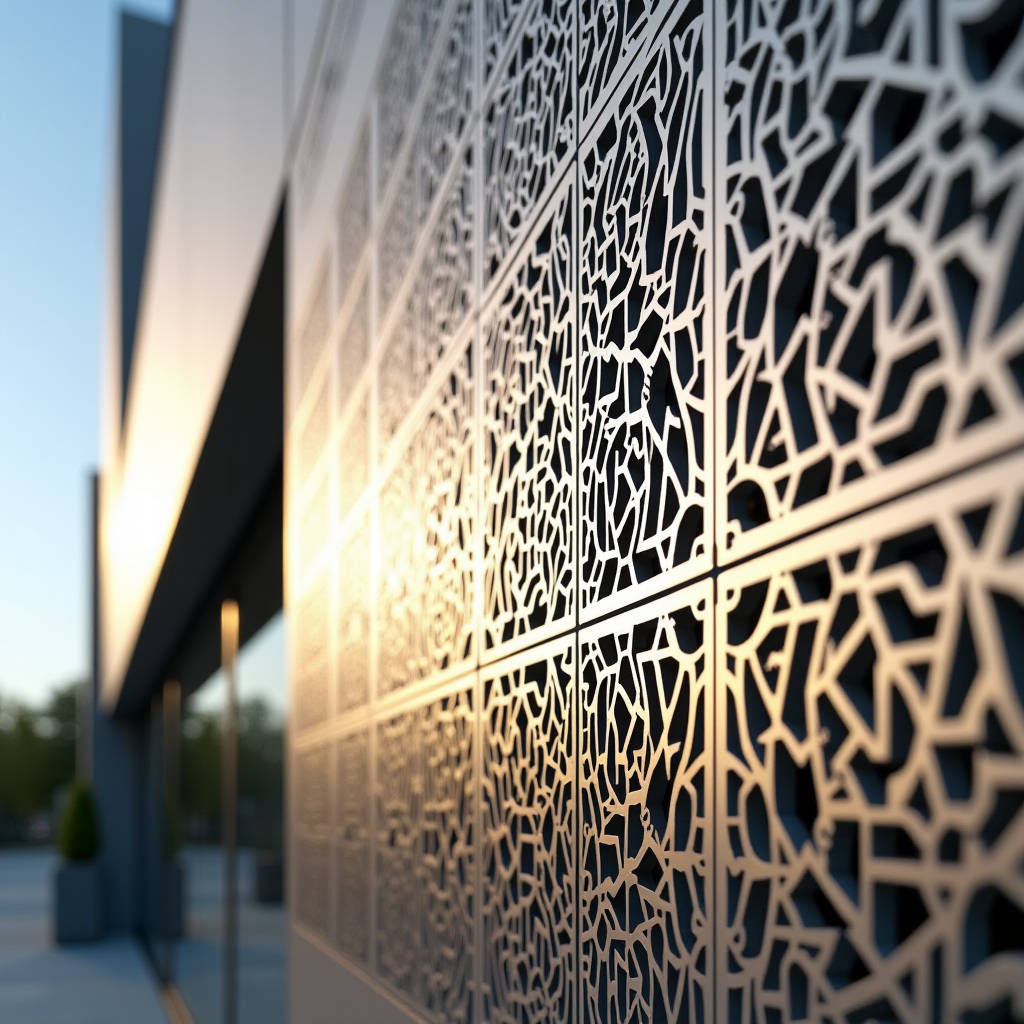
Procurement managers and façade contractors evaluating laser cut aluminum panel systems quickly discover that not all perforated metal cladding delivers the same structural integrity. A laser cut aluminum panel fabricated from solid 2.0mm, 2.5mm, or 3.0mm aluminium sheet offers a fundamentally different value proposition than expanded mesh, punched plate, or composite alternatives. The difference shows up in flatness tolerance across a 1200mm x 2400mm module, in weld consistency at the perimeter stiffener frame, and in how the panel handles wind load deflection after hundreds of thermal cycles. Getting the specification right at the tender stage determines whether the installed façade reads as a precise architectural surface or a wavy, oil-canning mess six months after handover.
What Separates Laser Cut Perforation From Other Metal Fabrication Methods
Laser cutting technology has been standard in precision sheet metal for decades, but applying it to architectural cladding at scale introduces constraints that shop drawing engineers deal with daily. The fundamental advantage of a fiber laser over turret punching or waterjet cutting on solid aluminium is edge quality. A properly dialed 3kW to 6kW fiber laser running on 2.5mm 3003-H14 alloy leaves a kerf edge that requires minimal secondary deburring — critical when the perforated pattern is the visual feature, not a hidden functional element.
Three parameters define the cut quality that specifiers should verify during the sample approval phase:
- Kerf width consistency: ±0.05mm across the full sheet. Wider variation indicates either worn optics or incorrect focal distance setting.
- Heat-affected zone (HAZ): On 2.0mm to 3.0mm aluminium, the HAZ should stay under 0.15mm. Beyond that, microstructural changes near the cut edge can create localized weakness that manifests as tear-out during high wind suction events.
- Dross adherence: Zero visible dross on the show face. Back-face dross under 0.1mm height is acceptable and will be hidden by the stiffener frame.
Turret punching remains viable for high-volume standard perforation patterns — 6mm round holes at 9mm staggered centers, for instance — but the tooling cost and pattern flexibility limitations make it unsuitable for custom architectural designs. Waterjet avoids the HAZ entirely but runs slower and leaves a rougher edge finish that requires more manual cleanup. For most architectural applications above 500m², fiber laser cutting hits the sweet spot between speed, precision, and cost per linear meter of cut.
Field Note: When reviewing laser cut samples from a prospective supplier, ask for a 300mm x 300mm corner sample with the specified stiffener frame attached. The laser pattern alignment relative to the folded edge reveals whether the fabricator uses a common datum point or relies on post-cut edge finding — the latter introduces cumulative error that becomes visible across a full elevation.
Material Selection: Why Solid Aluminium Alloy Matters for Perforated Panels
The alloy choice for a laser cut aluminum panel has direct consequences on perforation pattern integrity. The industry workhorse is 3003-H14, with 5005-H14 and 5052-H32 specified when higher tensile strength or marine-environment corrosion resistance is required. These are solid aluminium alloys — not laminated, not composite, not honeycomb-filled — and their mechanical properties remain consistent through the full sheet thickness.
Key mechanical values that affect laser cutting performance:
| Alloy & Temper | Tensile Strength (MPa) | Yield Strength (MPa) | Elongation (%) | Typical Application |
|---|---|---|---|---|
| 3003-H14 | 150–200 | ≥145 | 8–12 | Standard interior/exterior cladding |
| 5005-H14 | 160–210 | ≥150 | 6–10 | Coastal & high-humidity façades |
| 5052-H32 | 230–280 | ≥195 | 8–12 | High wind load zones, large-format panels |
For perforated panels specifically, elongation percentage matters. A pattern with fine filigree — say, 3mm-wide strands between elongated slots — requires enough ductility that the material doesn't micro-crack at the narrowest points during forming or thermal expansion. 3003-H14 at 8% elongation handles most architectural patterns without issue. But when the design pushes below 2.5mm strand width, switching to 5052-H32 with its higher elongation and tensile strength is cheap insurance against field failures.
The 5005 alloy sees increasing specification in Middle Eastern and Southeast Asian projects where the combination of UV exposure, salt spray, and humidity cycling demands better corrosion resistance than standard 3003. The magnesium content in 5005 (0.5–1.1%) provides that edge without the cost premium of full 5052.
Pattern Design Constraints That Shop Drawings Must Address
Architects tend to design perforation patterns in Rhino or Grasshopper without factoring in the physical limitations of a 2.0mm or 2.5mm aluminium sheet. The fabricator's shop drawing engineer then inherits the task of making the pattern buildable. Three constraints govern whether a laser cut pattern survives fabrication and installation:
Minimum Strand Width
The industry rule of thumb for solid aluminium cladding panels is a minimum strand width of 1.5x material thickness. For 2.5mm sheet, that means 3.75mm minimum between any two cut edges. Below that threshold, the panel becomes vulnerable to handling damage during crating and transport, and the stiffener frame's adhesive bond area shrinks to the point where flatness warranty becomes impossible to guarantee. Some fabricators — including Futeng® — will push to 1.2x material thickness for 5052-H32 with an engineered stiffener layout, but this requires project-specific mockup testing.
Open Area Percentage and Wind Load
Perforation open area directly reduces the panel's effective wind load area, which sounds like a structural benefit. The complication is that the remaining solid strands experience concentrated stress. A panel with 35% open area in a 6mm staggered round hole pattern behaves differently under negative wind pressure than a panel with 35% open area in a custom geometric pattern with irregular strand widths. Computational fluid dynamics (CFD) or at minimum a rationalized engineering judgment based on the smallest repeating pattern cell is necessary for patterns above 30% open area on panels exceeding 1.0m².
Pattern Registration Across Panel Joints
This is where laser cut panels either achieve architectural continuity or fail visibly. The pattern must register across the 15–20mm open joint between adjacent panels. Achieving this requires the fabricator to establish a consistent reference edge on every panel and to maintain pattern alignment within ±1.0mm across the full module dimension. The contractor's installation team must then maintain joint width tolerance within ±2mm — a coordination point that the specification should explicitly call out.
PVDF Coating Over Perforated Surfaces: The Process Sequence
The coating sequence for a laser cut aluminum panel is non-negotiable: cut first, then coat. Reversing this sequence — coating a full sheet and then laser cutting — leaves raw aluminium edges exposed at every perforation. Those edges will oxidize within weeks, creating visible white corrosion product that streaks down the façade with the first rain.
The standard architectural coating system for exterior solid aluminium cladding is a three-coat PVDF (polyvinylidene fluoride) system based on Kynar 500® or Hylar 5000® resin, applied per AAMA 2605 specification. The process on perforated panels introduces specific challenges:
- Pretreatment: A chromate conversion coating or chrome-free alternative must reach the interior surfaces of every perforation. Dip pretreatment is preferred over spray for perforated panels because it ensures complete coverage of cut edges.
- Primer coat: 5–10 microns DFT (dry film thickness). The primer must bridge the cut edge geometry without pulling back from sharp corners.
- Color coat: 25–35 microns DFT. Spray application on perforated panels requires adjusted gun angle and reduced fluid flow to avoid bridging across small perforations — a defect where paint webs across the hole instead of coating the interior edge.
- Clear coat: 15–20 microns DFT. Provides the UV resistance and gloss retention that the Kynar 500 system is specified for.
Total minimum DFT for AAMA 2605-compliant systems is 43 microns (1.7 mils). For projects within 500 meters of breaking surf or in industrial atmospheres with SO₂ exposure, specifying 55+ microns total DFT is prudent. The cost increment is marginal — roughly 8–12% on the coating line charge — but the service life extension in aggressive environments is documented in ASTM B117 salt spray testing data.
Pro Tip: During the sample approval stage, request a cross-section micrograph of a coated perforation edge at 50x magnification. The coating should wrap continuously around the cut edge with no visible thinning below 15 microns at the corner radius. If the supplier cannot provide this, their pretreatment or spray parameters are not dialed in for perforated work.
Stiffener Frame Design for Perforated Solid Aluminium Panels
Every laser cut aluminum panel above approximately 0.3m² requires a rear stiffener frame to maintain flatness. The perforation pattern complicates stiffener design because the bond area between the panel skin and the stiffener profile is reduced wherever perforations intersect the bond line.
Standard practice uses extruded aluminium hat-section or Z-section stiffeners, 25mm to 40mm deep, bonded to the panel rear face with structural adhesive — typically a two-part epoxy or modified silane polymer. The stiffener layout is calculated per panel dimensions and wind load requirements, but the perforation pattern overlay determines whether the standard stiffener grid works or needs adjustment.
For panels with irregular perforation patterns, the fabricator should provide a stiffener layout drawing that shows the actual bond area calculation. The minimum acceptable continuous bond width is 8mm. If the perforation pattern reduces bond width below this at any point along a stiffener, the stiffener must be shifted or a secondary stiffener added. This is a common source of variation between the architect's concept drawing and the approved shop drawing — and a reason to involve the fabricator early in the design development phase rather than at tender stage.
Packaging, Freight, and Site Handling for Perforated Cladding
Laser cut panels with fine perforation patterns are more vulnerable to handling damage than solid panels. The strands between perforations can bend or tear if the panel is lifted incorrectly or if packaging allows movement during container transit.
Standard export packaging for solid aluminium cladding panels shipped under FOB or CIF terms should include:
- Individual panel separation using closed-cell PE foam sheets, minimum 3mm thickness, placed between every panel face.
- Full-perimeter edge protection with rigid PVC or cardboard corner profiles.
- Palletized or crated stacking with maximum 20 panels per pallet for 2.5mm material, fewer for thinner gauges or high-open-area patterns.
- Moisture barrier wrapping — VCI (volatile corrosion inhibitor) film or desiccant packs inside sealed polywrap — for sea freight exceeding 21 days transit.
On site, the contractor should store crated panels flat on level supports, protected from direct rain exposure. The temptation to lean panels vertically against a wall to save floor space is a reliable way to introduce edge damage and pattern distortion before installation even begins.
Comparative Cost Drivers: Laser Cut vs. Standard Solid Panel
Procurement teams evaluating laser cut aluminum panel pricing need to understand what drives the cost delta over a standard unperforated solid aluminium panel. The table below breaks down the cost components for a typical 600m² façade package:
| Cost Component | Standard Solid Panel (2.5mm 3003, PVDF) | Laser Cut Panel (2.5mm 3003, PVDF, 25% Open Area) | Delta Driver |
|---|---|---|---|
| Raw aluminium sheet | $18–22/m² | $18–22/m² | Same base material |
| Laser cutting | N/A | $12–25/m² | Pattern complexity, total cut length |
| Deburring & edge cleanup | $2–3/m² | $5–8/m² | Perforation edges require manual or vibratory finishing |
| Pretreatment & PVDF coating | $15–20/m² | $18–25/m² | Dip pretreatment, adjusted spray parameters |
| Stiffener frame & bonding | $8–12/m² | $10–16/m² | Reduced bond area may require additional stiffeners |
| Packaging | $3–5/m² | $5–8/m² | Extra interleaving, more careful crating |
| Total ex-works range | $46–62/m² | $68–104/m² | 35–70% premium over standard panel |
These figures are indicative for a mid-complexity pattern at 600m² volume. Simple round-hole patterns at the lower end of the open-area range will price near the bottom of the range. Complex custom patterns with fine strands, high open area, and tight registration requirements push toward the upper end. Volume matters significantly — the laser cutting cost per square meter drops 20–30% when the order exceeds 1,500m² because setup and nesting optimization amortize across more panels.
Specification Checklist for Tender Documents
A well-written specification section for laser cut aluminum panel cladding prevents substitution games and ensures all bidders price the same scope. The following items should appear in the performance specification or the prescriptive specification, depending on project delivery method:
- Material: Solid aluminium alloy sheet, 3003-H14, 5005-H14, or 5052-H32 per ASTM B209. Thickness as indicated on shop drawings (2.0mm, 2.5mm, or 3.0mm). Aluminium composite panels are not acceptable as a substitution.
- Perforation method: Fiber laser cutting. Turret punching acceptable only for standard round-hole patterns with written approval. Waterjet acceptable with edge finish sample approval.
- Pattern tolerance: ±0.5mm on individual feature dimensions, ±1.0mm on pattern registration relative to panel edges.
- Coating: Three-coat PVDF system, Kynar 500 or Hylar 5000 resin, minimum 43 microns total DFT per AAMA 2605. Dip pretreatment mandatory for perforated panels.
- Flatness: Maximum deviation of 0.5% of panel diagonal dimension after stiffener attachment, measured per ASTM E1155 or equivalent.
- Wind load: Panel and anchoring system to resist design wind loads per project structural engineer's report, with deflection under service load limited to L/90.
- Mockup: Full-size mockup of minimum two panels with pattern continuity across joint, approved by architect prior to production release.
- Quality assurance: Mill test certificates for aluminium coil, coating batch certificates, laser cut first-article inspection report.
Including these items in the tender package does not guarantee a problem-free project, but it eliminates the most common sources of specification drift between the bid stage and the installed product.
How to Evaluate a Laser Cut Panel Supplier
Beyond price and lead time, several supplier attributes separate fabricators who deliver consistent quality from those who create site headaches. When qualifying a laser cut aluminum panel supplier — whether domestic or overseas — procurement teams should investigate:
Laser capacity and redundancy: A single 3kW fiber laser running one shift can handle roughly 400–600m² of medium-complexity perforation per month. For a 2,000m² project with a 10-week production window, the supplier needs either multiple machines or a clear subcontracting plan. Ask directly: "How many laser cutting hours per week are allocated to this project, and what is your backup if that machine goes down?"
Coating line capability: The maximum panel size that the coating line can handle determines whether large-format panels require joints. A line limited to 1,500mm width means 1,500mm x 3,000mm panels need a horizontal joint that a 2,000mm-capable line would avoid. This is a design constraint that should surface during supplier qualification, not during shop drawing review.
Export documentation experience: For international procurement, the supplier's familiarity with letter of credit requirements, certificate of origin documentation, and destination-country building code compliance testing (e.g., ASTM E84 for flame spread in the US market, EN 13501 for EU projects) directly affects whether the shipment clears customs without delays.
Futeng® has supplied laser cut aluminum panel systems to commercial façade projects across Southeast Asia, the Middle East, and Australia, with in-house fiber laser capacity and a PVDF coating line qualified to AAMA 2605. The value of working with a supplier that controls both cutting and coating under one roof is that responsibility for pattern-to-coating coordination sits with a single party — no finger-pointing between the laser house and the coating house when something goes wrong.
Common Non-Conformances and How to Catch Them Early
After reviewing defect reports from a decade of façade projects, certain patterns repeat. Knowing what to look for during factory inspection and site receiving reduces the chance that problems reach the installed façade:
- Pattern drift: The perforation pattern shifts relative to the panel edge by more than 1.5mm from one end to the other. Cause: the laser cutting program uses edge-finding on each sheet rather than a fixed datum, or the sheet was not square when loaded. Check: measure pattern-to-edge distance at all four corners during first-article inspection.
- Coating bridging: Paint webs across perforations, especially in slot patterns under 4mm width. Cause: excessive fluid flow or incorrect gun distance during spray application. Check: backlight the panel and look for closed holes; a 2mm pin gauge should pass through every perforation.
- Stiffener delamination: The stiffener frame separates from the panel skin, often starting at corners. Cause: insufficient adhesive coverage, contamination on bond surface, or thermal cycling beyond the adhesive's service temperature range. Check: tap-test stiffeners with a coin or small hammer; a dull thud indicates bond, a sharp rattle indicates delamination.
- Oil canning: Visible waviness across the panel face under certain lighting conditions. More common on large-format panels with high open area. Cause: residual stress in the aluminium sheet released during laser cutting, or insufficient stiffener rigidity. Check: view panels under oblique lighting at the factory; if oil canning is visible before shipping, it will be worse after installation.
Catching these issues at the factory is vastly cheaper than remediating on site. The cost of a factory inspection trip — flights, hotel, two days of an inspector's time — is typically less than 2% of the contract value and pays for itself if it prevents one batch of panels from being shipped with a systematic defect.
Lead Time Realities for Custom Perforated Façade Packages
Procurement schedules that treat laser cut aluminum panel procurement like a commodity material order are a recurring source of project delay. The realistic timeline from placement of order to delivery at site breaks down as follows for a 1,000m² custom perforation package:
- Shop drawing approval: 2–3 weeks. This assumes the architect reviews and returns drawings within one week. In practice, three rounds of comments are common.
- Sample/mockup approval: 2–3 weeks, concurrent with shop drawings if managed well. The mockup panel must be fabricated with the actual production tooling and coating batch to be representative.
- Material procurement: 2–4 weeks. Standard 3003-H14 coil is typically in stock at major mills. 5005 or 5052 in specific thicknesses may require mill rolling, adding 2–3 weeks.
- Laser cutting production: 3–5 weeks for 1,000m², depending on pattern complexity and machine capacity.
- Coating: 2–3 weeks, including pretreatment, primer, color, clear, and curing.
- Stiffener attachment and QC: 1–2 weeks.
- Packaging and container loading: 1 week.
- Ocean freight: 3–6 weeks depending on origin-destination pair.
Total realistic lead time: 14–22 weeks from order to site delivery. Projects that need panels in 10 weeks are possible only if the supplier has pre-approved stock material and the pattern is simple enough to cut and coat on an accelerated schedule — and even then, ocean freight time is the hard floor.
The laser cut aluminum panel segment rewards early supplier engagement. When the fabricator sees the pattern concept during design development rather than at tender, the feedback loop on buildability, cost, and lead time compresses by weeks. The specification becomes a collaboration rather than a wish list, and the installed façade is better for it.