Perforated Aluminum Cladding Engineering A Specifier Guide to Open Area Wind Load and Coating
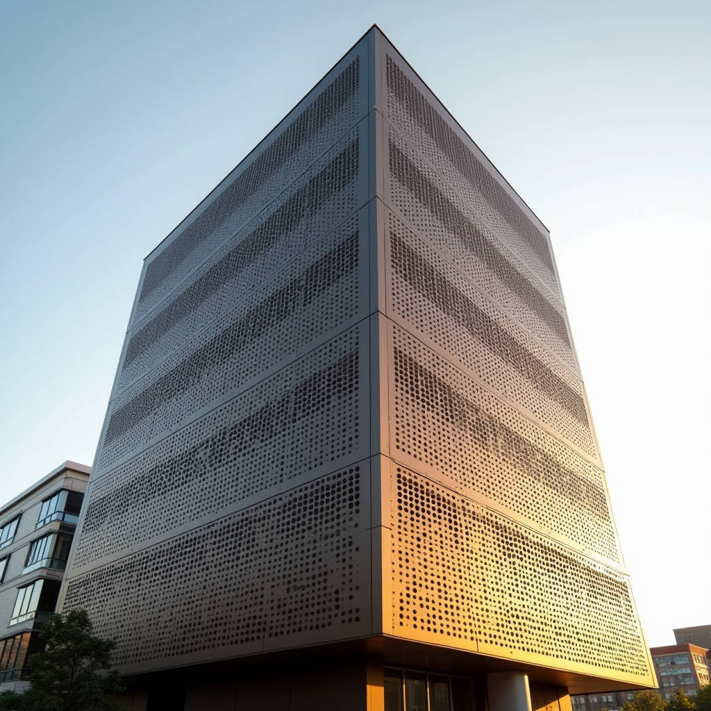
Perforated aluminum cladding has moved from a niche architectural accent to a structural and environmental workhorse on modern commercial facades. Contractors and specifiers increasingly turn to these panels to manage solar gain, daylight, acoustic performance, and wind pressure simultaneously, yet the engineering decisions behind them are rarely discussed in procurement meetings. The perforation ratio, hole geometry, sheet thickness, and coating system each change how the panel behaves under load and how it ages. This article walks through the measurable trade-offs, from open area calculations to PVDF film thickness, so that a project team can specify a perforated aluminum cladding system with confidence rather than guesswork.
Why Perforation Changes the Engineering Picture
A solid aluminum sheet is a predictable membrane. Add a field of holes and you introduce three variables that alter the panel's structural and thermal identity. First, the net section is reduced, so bending stiffness and load capacity drop in proportion to the open area. Second, the panel becomes a tuned surface for airflow and pressure equalization, which interacts with the cavity behind the rainscreen. Third, the perforations change solar absorptance and acoustic absorption in ways that a plain panel cannot match.
For a curtain wall or ventilated facade, the practical consequence is that a perforated aluminum cladding panel is rarely specified at the same gauge as a solid panel. A 2.0 mm solid sheet may be adequate for a given wind zone, but the same panel at a 40 percent open area may require 2.5 mm or 3.0 mm to maintain deflection limits. The table below summarizes typical engineering guidance for common perforation ratios.
| Open Area | Typical Sheet Thickness | Max Panel Width (mm) | Deflection Under 1.5 kPa (mm) | Relative Cost Index |
|---|---|---|---|---|
| 0% (solid) | 2.0 mm | 1200 | 2.1 | 1.00 |
| 20% | 2.0 mm | 1000 | 2.8 | 1.08 |
| 30% | 2.5 mm | 1000 | 2.4 | 1.22 |
| 40% | 3.0 mm | 900 | 2.6 | 1.45 |
These figures assume a 5052-H32 alloy, a 600 mm support spacing, and a fixed four-edge support condition. Actual values depend on the hole pattern, edge returns, and the stiffening ribs that a fabricator like Futeng® adds to large panels.
Hole Geometry and Open Area Calculation
The open area is not a stylistic choice; it is a calculated value that drives airflow, daylight transmission, and structural performance. For a staggered round hole pattern, the open area is approximately 90.7 percent of the theoretical maximum for a given pitch. Square and slotted patterns behave differently because the ligament between holes carries more load in one axis than another.
Specifiers should request the exact open area from the fabricator rather than relying on a visual guess. A 3 mm hole at 6 mm pitch and a 6 mm hole at 12 mm pitch both produce roughly a 23 percent open area, but the smaller holes create a finer visual texture and a different acoustic signature. The hole diameter also affects the panel's resistance to dirt accumulation and the coating's ability to cover the cut edge without runs.
Coating Systems and Edge Protection
Perforated panels expose the cut edge of the aluminum to the environment, and that edge is where corrosion and coating failure begin. The industry standard for exterior architectural aluminum is a two-coat or three-coat PVDF system per AAMA 2605, which specifies a minimum dry film thickness of 70 microns for the color coat on top of a primer. For perforated panels, the coating must also cover the inside of each hole, which is why the finishing process matters as much as the chemistry.
Fabricators apply PVDF after perforation so that the cut edges receive full coverage. When panels are perforated after coating, the exposed aluminum at each hole becomes a corrosion risk unless it is touched up. A reputable supplier will document the coating thickness on both the face and the hole walls, and will verify adhesion with a cross-hatch test per ASTM D3359.
Specify AAMA 2605 for any perforated panel that will face a coastal or industrial environment. The extra film thickness pays for itself in warranty claims avoided.
Acoustic and Thermal Performance
Perforated panels are frequently paired with acoustic insulation in the cavity to create a sound-absorbing facade. The open area percentage and the backing material determine the noise reduction coefficient. A 30 percent open area panel backed by a 50 mm mineral wool layer can achieve an NRC in the range of 0.70 to 0.85, which is useful near highways, rail lines, and mechanical plant rooms.
On the thermal side, perforation reduces solar absorptance because a portion of the incident radiation passes through the holes to the cavity, where it is dissipated rather than conducted into the building. Combined with a ventilated cavity, this can lower the peak surface temperature of the facade by several degrees Celsius, which reduces the cooling load and supports LEED points under the solar reflectance credit. The same mechanism, however, means the cavity must be designed to drain and dry, because the open holes allow moisture to enter the space behind the panel.
Wind Load and Pressure Equalization
A perforated panel is not a fully sealed rainscreen. The open area allows air to flow into the cavity, which changes how wind pressure is distributed across the panel and the substructure. In a pressure-equalized design, the cavity is deliberately vented so that the pressure behind the panel matches the pressure in front, reducing the net load on the cladding. A perforated panel achieves this naturally, but the designer must still account for the residual pressure difference and the flutter that can occur at the panel edges.
For high-rise projects, the wind tunnel data from the facade engineer should be reviewed against the panel's net section modulus. The effective thickness of a perforated panel is lower than its nominal gauge, and the deflection limit of L/180 for aluminum curtain wall per AAMA standards will often govern the design before the stress limit is reached.
Installation and Substrate Considerations
Perforated panels are installed with the same concealed clip or exposed fastener systems used for solid panels, but two details deserve attention. First, the clip spacing must be reduced when the open area is high, because the panel flexes more between supports. Second, the cavity behind the panel must be kept clear of debris, because the holes will collect dust and leaves that can block drainage.
The substructure is typically a galvanized or stainless steel frame with aluminum brackets. Dissimilar metal contact between the aluminum panel and steel frame must be isolated with a gasket or a powder-coated spacer to prevent galvanic corrosion. The panel's edge returns, usually 20 to 30 mm, add stiffness and create the shadow line that gives the facade depth.
Cost Drivers and Procurement Advice
The cost of a perforated aluminum cladding system is driven by three factors: the open area (which increases material waste and machining time), the sheet thickness (which increases material weight), and the coating specification. A 40 percent open area panel can cost 40 to 50 percent more than a solid panel of the same gauge, before considering the added stiffening required.
For a project team evaluating suppliers, the practical checklist includes a written confirmation of the open area, a coating thickness certificate, a sample of the hole edge quality, and a deflection calculation for the worst-case wind zone. Futeng® provides these documents as standard for every perforated panel order, which removes the guesswork from the procurement stage.
Standards and References
Specifiers should anchor the design to recognized standards. The coating performance is defined by AAMA 2605, the structural design of aluminum by the Aluminum Association design manual, and the alloy chemistry by ASTM B209. Acoustic performance testing follows ASTM C423, and the perforation open area can be verified against the manufacturer's published data. These references give the project team a defensible basis for the specification.
Final Engineering Guidance
The decision to use perforated aluminum cladding should be driven by the project's performance targets, not by aesthetics alone. Define the open area from the daylight and acoustic goals, then verify that the panel thickness and support spacing meet the wind load deflection limits. Confirm the coating system covers the hole walls, and specify a ventilated, drained cavity that handles the moisture the perforations admit. With those four checks in place, a perforated facade delivers the visual interest and environmental performance that a solid panel cannot, at a predictable cost and with a service life that matches the rest of the building envelope.