Perforated Aluminium Cladding Engineering The Open Area Ratio Wind Load and Coating Decisions That Define Facade Performance
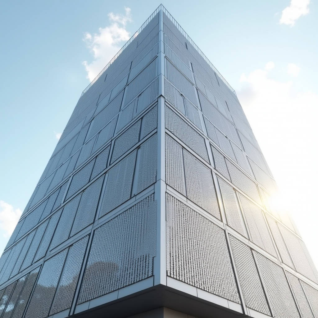
Perforated aluminium cladding has moved from a decorative niche into a mainstream facade strategy for commercial towers, transit hubs, and industrial plants. The appeal is straightforward: a precision-punched solid aluminium sheet that filters daylight, manages solar gain, and screens unsightly equipment while keeping the building envelope light and corrosion-resistant. But the real engineering value sits below the surface. Open area ratio, hole geometry, sheet gauge, and coating system determine whether a facade performs or fails. Procurement teams that treat perforated panels as a simple aesthetic product often discover later that wind load assumptions, acoustic targets, or thermal calculations were built on the wrong numbers. This article walks through the technical decisions that matter when specifying perforated aluminium cladding for a real project, with the data needed to defend those choices in front of an architect, a structural engineer, and a client.
Why the Perforation Pattern Is a Structural Decision
Every hole removes material from the sheet, and the pattern dictates how much stiffness and strength remain. The open area ratio, expressed as a percentage of the panel face, is the first number a structural engineer will ask for. A 40% open area panel carries far less load in its plane than a 15% panel, and the difference changes the required substrate, the framing spacing, and the fastener pattern.
For a solid aluminium cladding panel, the base sheet is typically 2.0 mm, 2.5 mm, or 3.0 mm thick. Perforating that sheet reduces its effective section. The European standard EN 1999-1-1 (design of aluminium structures) and the US AAMA 508-07 test procedure for pressure-equalized and non-pressure-equalized wall systems both expect the specifier to account for net section reduction. In practice, a 3.0 mm panel with a 25% open area can match the stiffness of a 2.0 mm solid panel, but only if the hole pattern is staggered and the edge zones are kept free of perforation.
Keep the outer 100 mm band of each panel unperforated. This preserves the load path to the fixing points and prevents the panel from tearing at the corners under wind suction. It also gives the fabricator a clean surface for folding returns and for the concealed fixing brackets.
Open Area Ratio and Its Real-World Consequences
The open area ratio is not just a visual choice. It drives three separate performance streams that often conflict. A higher open area gives better natural ventilation and daylight diffusion, but it weakens the panel, reduces acoustic isolation, and changes the wind load coefficient on the building. A lower open area protects privacy and blocks solar radiation but reduces airflow and adds weight to the facade system.
For a typical office tower in a temperate climate, a 25% to 35% open area on a 2.5 mm panel balances daylight control with structural safety. For a plant room screen or a car park facade, where ventilation is the priority and people are not working directly behind the wall, a 40% to 50% open area on a 3.0 mm panel is common. The table below summarises the trade-offs a specifier should check before committing to a pattern.
| Open Area Ratio | Typical Sheet Gauge | Primary Benefit | Structural Note | Common Use |
|---|---|---|---|---|
| 15% - 20% | 2.0 mm | Privacy, solar shading, visual texture | Close to solid panel behaviour; minimal framing changes | Office spandrels, hotel balconies |
| 25% - 35% | 2.5 mm | Balanced daylight, ventilation, and strength | Net section reduction must be checked in wind load design | Office towers, transit stations |
| 40% - 50% | 3.0 mm | Maximum airflow and acoustic absorption with backing | Requires reinforced framing and tighter fixing centres | Plant screens, car parks, industrial facades |
Hole Geometry and Pattern Selection
Round holes are the default because they are the easiest to punch and the most predictable in terms of strength loss. Square, slotted, and custom shapes are possible, but each adds tooling cost and reduces the panel's residual strength for the same open area. A staggered round-hole pattern is structurally superior to a square grid because it distributes the removed material more evenly across the sheet.
Hole diameter also matters. A 5 mm hole at a tight pitch reads as a fine mesh from a distance, while a 20 mm hole at a wide pitch reads as a bold architectural statement. The same open area can be achieved with very different hole sizes, and the visual result is completely different. Make the decision on hole size early, because it affects the minimum sheet gauge. A 3.0 mm sheet can carry a 20 mm hole comfortably, but a 2.0 mm sheet with the same hole may deform at the edges during punching.
Specify the perforation to be punched before the sheet is folded and coated. Punching after forming distorts the panel, and punching after coating destroys the PVDF film at the hole edges, leaving exposed aluminium that will corrode. The fabrication sequence is a quality gate that a good supplier will control without being asked.
Coating Systems for Perforated Panels
The perforated panel has more edge surface area than a solid panel of the same footprint, because every hole adds a cut edge. Those edges are the weak point for corrosion, so the coating system is not a cosmetic choice. A 70% PVDF (polyvinylidene fluoride) coating, applied to a minimum dry film thickness of 25 microns, is the industry standard for exterior architectural aluminium. The AAMA 2605 specification covers the highest-performance exterior coatings and is the benchmark for facade panels that must hold colour and gloss for decades.
For perforated panels, the coating must wrap into the hole edges. Specify that the coating is applied after perforation and that the fabricator verifies edge coverage on a sample. Bare aluminium edges inside the holes will oxidise unevenly and create a visible halo around each perforation within a few years in a coastal environment. A 2.5 mm or 3.0 mm sheet gives the coating more material to grip at the hole edge than a thin gauge, which is another reason to avoid going below 2.0 mm on exterior perforated work.
Wind Load and Fixing Design
Perforated panels are often treated as solid panels in wind load calculations, which is conservative but can be wasteful. The perforations allow air to pass through, which reduces the net pressure on the panel in many conditions. However, a fully sealed building with perforated panels on one face can still develop significant pressure on that face, so the safe approach is to design for the worst case and confirm with the structural engineer.
The fixing pattern must be adjusted for the net section. A solid panel of 2.5 mm can be fixed at 600 mm centres, but a 40% open area panel of the same gauge may need 400 mm centres or a thicker sheet. The fastener itself should be stainless steel, and the fixing points should always sit in the unperforated edge band. The AAMA 508-07 test method provides a practical way to verify the performance of the assembled system before it goes on site.
Acoustic Performance and the Backing Question
Perforated panels are often specified for acoustic control, but the panel alone does very little. The perforation only becomes an acoustic absorber when it is backed by a cavity and a porous material such as mineral wool. The open area ratio, the hole diameter, and the depth of the cavity all determine the frequency range that the system absorbs. A 23% open area panel with a 50 mm mineral wool backing absorbs mid-frequency noise well, which is why it is common in plant rooms and transit stations.
If acoustic performance is a requirement, specify the full assembly, not just the panel. Ask the supplier for test data from an accredited laboratory, and make sure the backing material is fire-rated to the local standard. A perforated panel that is not backed is a visual and ventilation feature, not an acoustic product, and it should be specified as such.
Procurement and Quality Control
Perforated aluminium cladding is a fabricated product, and the quality varies widely between suppliers. The three checks that matter most are the alloy, the coating, and the perforation tolerance. The alloy should be a 5000-series or 3000-series aluminium suitable for exterior use, with a temper that holds its shape after punching and folding. The coating should meet AAMA 2605 for exterior panels, and the perforation tolerance should be verified against the approved sample.
For a project with tight delivery windows and a large panel count, working with a supplier that controls the full process from sheet to coated panel to fixing system reduces coordination risk. A manufacturer such as Futeng® runs the perforation, folding, and coating in-house, which shortens lead times and keeps the tolerance stack consistent across a large facade. That level of control matters when thousands of panels must line up on a tower.
Installation and Maintenance Considerations
Perforated panels are lighter than solid panels of the same footprint, which reduces crane and scaffold loads, but they also collect dust and dirt in the holes. In a polluted or coastal environment, the perforations can stain if the coating is not maintained. Specify a PVDF coating with a self-cleaning or low-friction topcoat, and plan for periodic washing of the facade. The open area also means that the cavity behind the panel is ventilated, which helps manage condensation but requires a proper drainage detail at the base of the wall.
Access for maintenance is simpler with a concealed fixing system, because panels can be removed without disturbing the neighbours. Specify a panel removal procedure in the O&M manual, and make sure the fixing hardware is standardised so that replacement panels are easy to source.
Cost Drivers and Budget Realism
Perforation adds cost to a solid aluminium panel, and the cost scales with the complexity of the pattern and the open area ratio. A simple round-hole pattern at 20% open area adds a modest premium, while a custom shape at 45% open area with a tight tolerance can add significantly. The sheet gauge is the second cost driver, because thicker sheet costs more and reduces the number of panels per tonne. The coating system is the third, with AAMA 2605-grade PVDF sitting at the top of the price range.
Budget realistically by asking the supplier for a price per square metre at the final open area ratio and gauge, not for a generic perforated panel price. The difference between a 2.0 mm and a 3.0 mm panel at the same open area can be several percent of the total facade budget, and that difference is often larger than the cost of the perforation itself.
Closing Engineering Advice
Specify perforated aluminium cladding with the open area ratio, hole geometry, sheet gauge, and coating system defined as engineering parameters, not as visual preferences. Confirm the net section reduction with the structural engineer, verify the acoustic assembly if sound control is required, and require accredited test data from the supplier. Keep the outer edge band unperforated, coat after punching, and use a 5000-series alloy with an AAMA 2605 PVDF finish. A perforated facade specified this way delivers daylight, ventilation, and visual interest without compromising the structural and weather performance of the building envelope. That is the difference between a panel that merely looks perforated and one that performs as a designed component of the facade system.