Specifying an Aluminium Sheet with Holes for Facades, Wind Load and Acoustic Performance
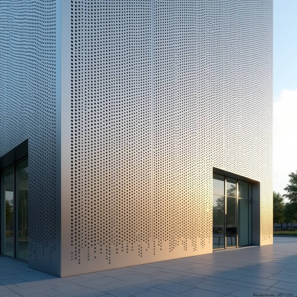
An aluminium sheet with holes is no longer a simple filtration or screening product. Across commercial facades, sunshades, acoustic barriers, and ventilation screens, perforated solid aluminium has become a structural and aesthetic workhorse. The engineering challenge is not whether to use it, but how to specify the hole geometry, open area, alloy, and coating so that the panel performs across wind load, acoustic, and visual requirements. This article walks through the practical specification decisions for a solid aluminium sheet with holes, with emphasis on the parameters that actually move cost and performance on a real project.
Why a Solid Aluminium Sheet with Holes Differs from Other Perforated Products
Most suppliers sell perforated metal as a commodity. The distinction matters on a facade because the panel must carry wind load, resist corrosion, and hold a finish for decades. A solid aluminium sheet with holes retains the full structural thickness of the base plate, so the open area reduces stiffness but the residual ligament between holes still carries real load. The common alloys are 3003, 5052, and 6061, each with a different yield strength and corrosion profile. For exterior cladding, 5052-H32 or 3003-H14 are the usual choices because they balance formability with strength after punching.
Open area is the single most influential parameter. It controls daylight transmission, acoustic absorption, wind pressure, and the visual rhythm of the facade. A 40 percent open area panel will behave very differently from a 60 percent panel under the same wind load. The structural engineer needs the open area and hole pattern before any deflection calculation can be trusted.
Hole Geometry, Stagger, and Open Area
Round holes in a 60-degree staggered pattern are the industry default, and for good reason. Staggering increases the number of openings per square metre compared with straight rows, which raises the open area for a given hole diameter and pitch. The standard relationship is simple: open area equals the ratio of hole area to the area of the repeating cell. For a 60-degree stagger, the open area is calculated as 90.7 percent of the hole-to-pitch ratio squared.
Slotted and square holes are used when the project needs directional airflow or a specific visual texture, but they concentrate stress at the corners and reduce the usable ligament. Round holes distribute stress more evenly and are the most predictable for structural analysis. For acoustic panels, the hole diameter and open area are tuned against the cavity depth behind the panel. A common starting point is a 3 mm to 5 mm hole with a 40 to 50 percent open area backed by a 50 mm to 100 mm air cavity.
Thickness, Alloy, and the Limits of Punching
Panel thickness on a solid aluminium sheet with holes typically runs from 2.0 mm to 3.0 mm for facade applications. Thicker material resists buckling and reduces the number of stiffeners needed, but it also raises weight and cost. A 3.0 mm 5052 panel has roughly 50 percent more flexural stiffness than a 2.0 mm panel of the same geometry, which can eliminate intermediate supports on a large module.
Punching limits are set by the ratio of hole diameter to sheet thickness. A hole smaller than about 1.5 times the sheet thickness risks tool wear and burr formation. For a 3.0 mm panel, the practical minimum hole is around 4.5 mm to 5 mm. If the design calls for fine perforation, the panel must be thinner or the holes must be enlarged. This is a frequent source of friction between architects and fabricators, so it is worth settling the hole-to-thickness ratio before the drawing is frozen.
Coating and Corrosion Strategy
The punched edges expose fresh aluminium, and the cut faces are the first place corrosion starts if the coating is thin or damaged. For exterior use, a PVDF (70/30) two-coat or three-coat system is the standard, with a dry film thickness of about 25 to 35 microns. The coating must wrap the hole edges, which means the fabricator needs to pay attention to edge coverage during spray application. Powder coating is a cost-effective alternative for interior or sheltered locations, but it is less weather-resistant than PVDF over a 20-year service life.
Anodising is another option, but the punched edges anodise to a slightly different tone than the flat face, which can be visible on a tight grid. If the project demands a uniform metallic look, PVDF is the safer choice. The coating spec should reference the relevant performance tests, including salt spray and UV exposure, so the buyer can verify the film thickness at the factory.
Wind Load and Structural Design
Perforation changes the wind response of a panel in two ways. First, the reduced solid area lowers the net pressure on the panel, but the panel must still be designed for the peak local pressures that occur at edges and corners of the building. Second, the holes allow air to pass through, which can reduce the net wind load compared with a solid panel of the same area. The effective wind area used in the calculation should be based on the solid area, not the gross panel dimensions.
Deflection limits for perforated panels are usually set at L/60 to L/90 for facade applications, depending on the visual tolerance of the grid. The structural engineer should model the panel with the actual open area and hole pattern, because a simple solid-plate model will overestimate stiffness. The fixings and the perimeter frame carry the load into the substructure, so the edge detail is as important as the panel itself.
| Parameter | Typical Range | Engineering Note |
|---|---|---|
| Panel thickness | 2.0 – 3.0 mm | 3.0 mm reduces stiffener count by ~50% |
| Hole diameter | 3 – 12 mm | Min hole ≈ 1.5 × sheet thickness |
| Open area | 30 – 60% | Drives wind, acoustic, and daylight performance |
| Alloy | 3003-H14, 5052-H32 | 5052 preferred for coastal exposure |
| Coating | PVDF 70/30, 25–35 µm | Edge coverage critical at hole rims |
| Deflection limit | L/60 – L/90 | Model with actual open area |
| Acoustic cavity | 50 – 100 mm | Backed cavity absorbs mid-frequency noise |
Acoustic Performance and the Cavity Detail
When the brief includes noise control, the aluminium sheet with holes is typically the facing of a sound-absorbing assembly. The hole diameter and open area are matched to the frequency range of the noise source. Smaller holes with a lower open area absorb higher frequencies, while larger holes with a higher open area favour lower frequencies. The air cavity behind the panel acts as a resonator, and its depth is tuned to the target band. A 50 mm cavity with a 40 percent open area panel is a workable starting point for general traffic noise, but the final design should be validated with impedance tube measurements.
The acoustic liner, usually a non-combustible mineral wool or similar, sits behind the panel and must be protected from moisture and mechanical damage. The perforation density and the liner together determine the absorption coefficient, and both should be specified together rather than treated as independent choices.
Fabrication Tolerances and Quality Control
Burr height, hole position tolerance, and flatness are the three quality metrics that matter most. A burr on the hole edge will catch the coating and create a corrosion path, so the fabricator should deburr the panel after punching. Hole position tolerance is typically ±0.5 mm across the panel, and flatness is checked against a straightedge. For large panels, the punching process can introduce local distortion, so the panel should be stress-relieved or flattened before coating.
Futeng® supplies solid aluminium cladding panels with holes to facade contractors, and the practical lesson from production is that the hole pattern and the coating spec must be locked before the die is cut. Changing the hole diameter after tooling is expensive, so the buyer should confirm the open area and pattern against the acoustic and wind calculations early in the programme.
Reference Standards and Independent Verification
Specifiers should anchor the design to recognised references. The aluminium alloy and temper follow the relevant international alloy designation system, and the coating performance can be checked against the AAMA 2605 specification for high-performance organic coatings on architectural aluminium. The salt spray and UV durability requirements in that document give a measurable target for the finish. For structural design, the perforated panel can be treated with the same load combinations used for solid cladding, with the open area applied to the pressure coefficient. The American Architectural Manufacturers Association and the associated test methods provide a consistent basis for verifying both the coating and the panel performance.
Independent testing of a production sample is worth the cost. A single panel can be checked for film thickness, adhesion, and salt spray resistance, and the acoustic absorption can be measured in a laboratory. This verification catches problems before the panels are installed, which is far cheaper than reworking a facade after erection.
Practical Specification Checklist
- Confirm the hole-to-thickness ratio before freezing the drawing.
- State the open area and 60-degree stagger in the performance spec, not just the hole diameter.
- Specify 5052-H32 for coastal or high-humidity projects.
- Require PVDF edge coverage at the hole rims and a film thickness check.
- Model the panel with the actual open area for wind deflection.
- Match the acoustic cavity depth to the target frequency band.
- Set a burr-height limit and a flatness check in the quality plan.
Closing Recommendation
A solid aluminium sheet with holes performs well when the open area, alloy, thickness, and coating are specified as one coherent system rather than as independent line items. Lock the hole geometry early, verify the coating at the hole edges, and model the wind load with the true open area. On that basis, the perforated panel will deliver the acoustic, visual, and structural performance the project expects, with a service life measured in decades.