Perforated Metal Panel Facade Engineering Open Area Wind Load and Drainage
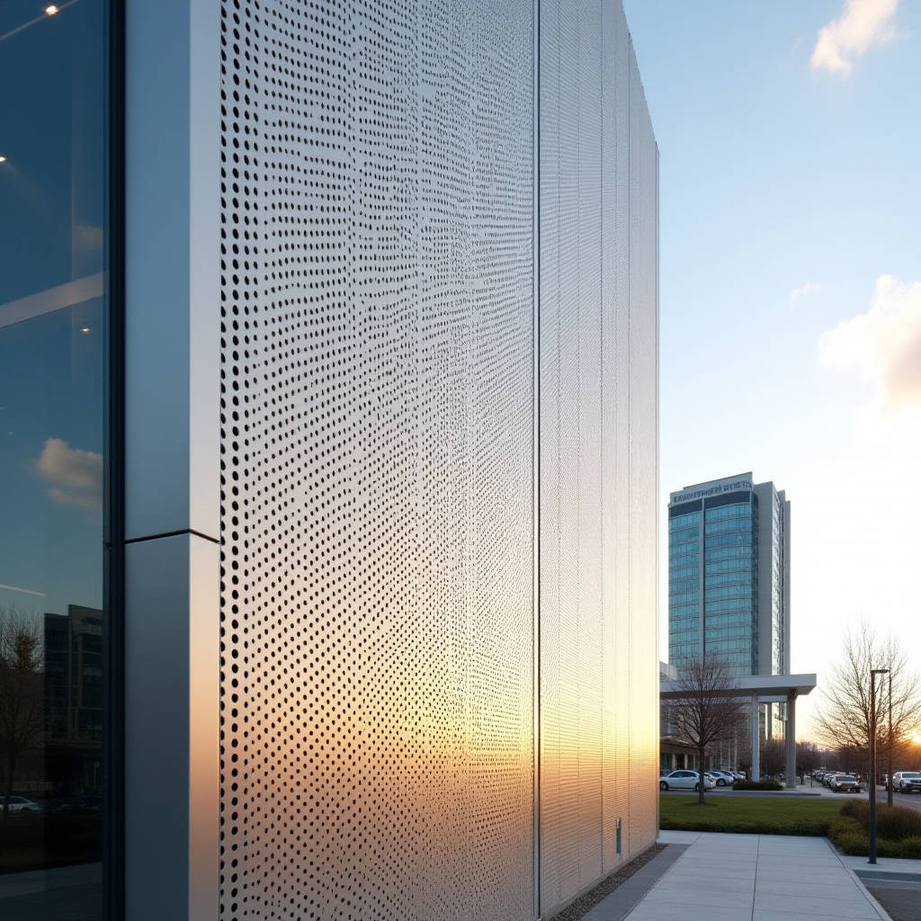
A perforated metal panel facade is no longer a decorative afterthought in modern envelope design. Across commercial towers, parking structures, cultural centers, and transit hubs, architects and contractors are specifying precision-punched aluminium panels to control daylight, manage airflow, and cut noise while keeping a clean visual line. The engineering reality, however, is that a perforated skin behaves differently from a solid cladding panel. Open area ratios, hole geometry, and panel stiffness all shift wind load, acoustic, and thermal performance. This article walks through the load paths, fabrication tolerances, and installation sequences that determine whether a perforated metal panel facade performs as specified or becomes a maintenance liability. The focus stays on solid aluminium sheet, not composite panels, so the numbers reflect real 2.0 to 3.0 mm plate behavior.
Why Perforation Changes the Engineering Picture
Cutting a pattern of holes into a solid aluminium sheet removes material and redistributes stress. A solid 3.0 mm panel carries wind load across its full section. A perforated panel with a 40 percent open area carries roughly 60 percent of the section, so the remaining ligament must resist the same design pressure. The first mistake contractors make is treating a perforated metal panel facade as a lighter version of a solid panel. It is not. The stiffness drops disproportionately because the removed material weakens the plate in bending more than in simple tension.
For a typical 1500 mm by 3000 mm panel supported on four edges, a solid 2.5 mm aluminium panel deflects noticeably less than a perforated panel of the same thickness at the same wind load. The practical response is not always to increase thickness. Often the correct fix is to add stiffening ribs, reduce the unsupported span, or specify a denser pattern with smaller holes. The open area ratio, hole diameter, and stagger pattern all feed into the effective elastic modulus that the structural engineer must use in the wind load calculation.
Open Area Ratio and Its Real Consequences
The open area ratio is the single most important variable in a perforated metal panel facade. It controls ventilation, daylight transmission, acoustic transparency, and structural stiffness simultaneously. A 20 percent open area behaves almost like a solid panel for wind purposes but offers little airflow. A 60 percent open area gives strong natural ventilation but requires careful stiffening and can transmit more solar heat into the cavity behind the panel.
For parking garage facades and sunshade screens, designers commonly target 40 to 55 percent open area. For acoustic barriers and privacy screens, the pattern moves toward smaller holes with lower open area, often 25 to 35 percent. Each choice changes the panel's ability to shed wind load and the amount of negative pressure that builds behind the skin. The cavity depth between the perforated skin and the backup wall becomes a design parameter, not an accident.
Hole Geometry and Ligament Width
Round holes are the most economical to punch and the most common. Square, slotted, and custom shapes cost more because tooling is specific and punching speeds drop. The ligament width, the solid strip between adjacent holes, controls the panel's structural continuity. A ligature below 1.5 times the sheet thickness risks tear-out at the hole edge during fabrication and reduces fatigue life under wind flutter.
For a 2.5 mm aluminium sheet, a practical minimum ligament is around 4 mm. This keeps the punched edge stable and prevents micro-cracks that propagate under repeated wind loading. When the open area pushes past 50 percent, the ligament narrows and the panel loses stiffness quickly. At that point, the engineer should either increase sheet thickness to 3.0 mm or add a stiffening frame.
Wind Load and Flutter Behavior
Perforated panels are more susceptible to flutter and edge vibration than solid panels because the airflow through the holes creates pressure fluctuations on both faces. The American Society of Civil Engineers (ASCE 7) wind provisions and the European EN 1991-1-4 both require the designer to account for the net pressure coefficient on a porous skin. A perforated metal panel facade with high open area can experience local negative pressures that exceed the values used for a solid cladding of the same footprint.
Field data from installed parking garage screens shows that the highest damage risk sits at the panel corners and edges, where the pressure coefficient peaks. Stiffening the perimeter and fixing the panel with concealed brackets that allow thermal movement reduces the flutter amplitude. The panel's natural frequency must stay well above the vortex shedding frequency of the hole pattern, otherwise the skin vibrates audibly and can fatigue the fasteners over years of service.
Acoustic Performance
A perforated metal panel facade doubles as an acoustic absorber when backed by a cavity filled with mineral wool or a similar porous medium. The hole pattern and open area determine the absorption coefficient across the frequency range. Small holes with lower open area absorb mid and high frequencies well. Larger holes with higher open area shift the absorption peak toward lower frequencies, which is useful for traffic noise barriers.
For a noise barrier application, the panel's open area typically sits between 30 and 40 percent, and the cavity depth is tuned to the dominant noise frequency. A 100 mm cavity with a 35 percent open area panel absorbs well in the 500 to 1000 Hz range, which covers most road traffic noise. The acoustic lining must be protected from moisture and insects, so a perforated metal face with a hydrophobic backing sheet is standard practice.
Material Grades and Coating Systems
Solid aluminium sheet for perforated panels is normally 5000 or 6000 series alloy. The 5052 alloy offers good corrosion resistance and formability, while 6061-T6 provides higher strength for large panels with high open area. Stainless steel is specified where impact resistance or a specific finish is required, but aluminium dominates because of weight and cost.
The coating system follows the same logic as solid cladding. A two-coat PVDF system at 20 to 25 microns total film thickness handles most exterior projects. A three-coat fluoropolymer system with a primer, color coat, and clear topcoat reaches 30 to 35 microns and offers better color retention in harsh coastal or industrial environments. The American Architectural Manufacturers Association (AAMA 2605) specification is the benchmark for high-performance fluoropolymer coatings, and it is the right reference for a perforated metal panel facade exposed to strong UV and salt.
| Coating System | Total Film Thickness | Salt Spray Resistance | Color Retention | Typical Use |
|---|---|---|---|---|
| Two-coat PVDF | 20-25 microns | 4,000 hours | Good, 5-year warranty | Standard commercial facades |
| Three-coat PVDF (AAMA 2605) | 30-35 microns | 4,000+ hours | Excellent, 10-year warranty | Coastal, high-UV, iconic projects |
| Polyester | 20-25 microns | 1,000 hours | Fair, 3-year warranty | Interior or low-exposure zones |
| Anodized (Class I) | 18-25 microns | Varies by seal | Metallic, stable | Architectural metal, interior |
Fabrication Tolerances and Punching Quality
Punching accuracy determines whether the pattern lines up across panel joints. A perforated metal panel facade with a mismatched pattern at the seam reads as a defect from street level. The industry standard for hole position is plus or minus 0.5 mm over a 3000 mm panel length, and the hole diameter tolerance is typically plus or minus 0.1 mm. CNC turret presses hold these tolerances, but the sheet must be held flat during punching to avoid distortion that shows up after installation.
Burr height on the punched edge matters for both safety and coating adhesion. A burr above 0.1 mm catches coating powder and creates a thin spot at the hole edge, which becomes a corrosion initiation point. Deburring or a secondary finishing pass is standard for architectural grade panels. The punched sheet should be degreased and pretreated before coating, because the oil from the punching process contaminates the surface if not removed.
Installation and Drainage
The cavity behind a perforated metal panel facade is a wet environment. Rain drives through the holes, and condensation forms on the back face. The drainage strategy must be designed into the system, not improvised on site. A continuous drainage channel at the base of each panel bay, with weep holes at the lowest point, prevents water from pooling against the backup wall. The backup wall itself needs a water-resistive barrier, because the perforated skin is not a water barrier.
Concealed fixing systems with sliding brackets allow the panel to expand and contract with temperature without buckling. Aluminium expands roughly 23 microns per meter per degree Celsius, so a 3000 mm panel moves about 2 mm across a 30 degree temperature swing. The bracket slots must accommodate this movement or the panel will bow and the coating will stress-crack at the fasteners.
Cost Drivers and Budget Reality
Unit cost for a perforated metal panel facade rises with open area, hole density, and pattern complexity. A standard round-hole pattern at 35 percent open area on 2.5 mm aluminium with a two-coat PVDF finish lands in a moderate range. Increasing to 50 percent open area with a custom pattern and a three-coat AAMA 2605 finish can push the cost up by 30 to 40 percent because of slower punching, more material removed, and higher coating specification.
Panel size also drives cost. Oversized panels reduce joint count and installation labor but require thicker sheet or additional stiffening, which raises material cost. The economic optimum for most projects sits between 1200 mm and 1500 mm in width and 2500 mm to 4000 mm in height, depending on the structural grid and the lifting capacity on site.
Procurement and Quality Control
Because perforation tolerance and coating quality are hard to verify after installation, the procurement contract should include a sample panel approval step. The approved sample fixes the hole pattern, open area, coating color, and finish gloss. Batch testing should cover film thickness, color delta, and salt spray performance. A responsible supplier such as Futeng® can provide mill certificates and coating test reports that match the AAMA 2605 requirements, which shortens the approval cycle for the contractor and the architect.
For international projects, verify that the panel supplier's fabrication capacity matches the project schedule. Punching large open areas is slower than flat sheet production, so lead times stretch. A realistic procurement plan adds two to three weeks over solid panel lead times for pattern approval and punching tooling.
Closing Recommendations
A perforated metal panel facade rewards teams that treat the perforation pattern as a structural and environmental variable, not just a visual one. Lock the open area ratio and hole geometry early, because they drive wind load, acoustic, and thermal behavior. Specify a coating system that matches the exposure, and hold the supplier to AAMA 2605 film thickness and salt spray numbers. Design the cavity drainage and thermal movement before fabrication, and approve a physical sample before mass production. With these steps, the perforated skin delivers ventilation, daylight, and visual interest without turning into a maintenance problem. The engineering effort spent up front is the difference between a facade that performs for decades and one that needs rework in the first warranty period.