Engineering Perforated Aluminum Sheet Metal Facades for Wind Load and Long Term Durability
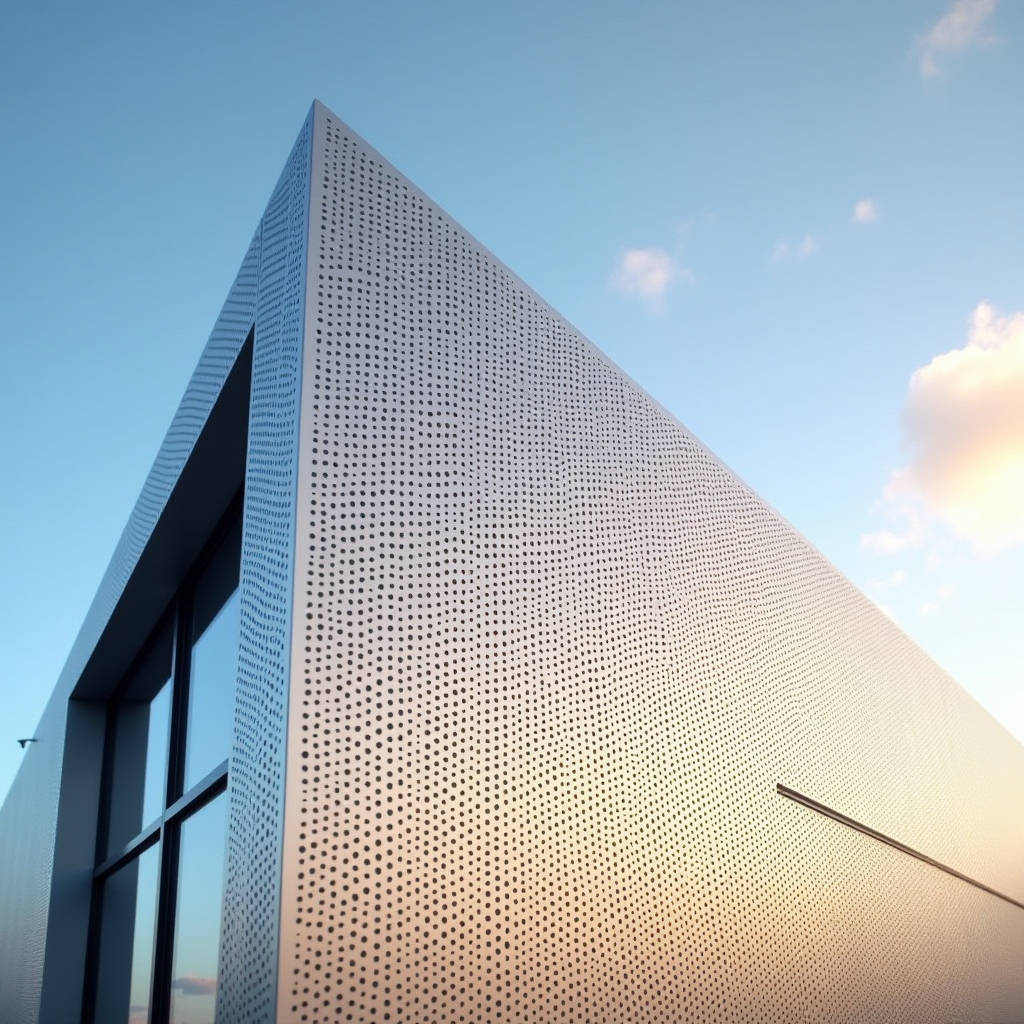
Perforated aluminum sheet metal has moved well beyond decorative screening into a structural role on modern facades, sunscreens, and ventilation cladding. The engineering question most procurement teams and facade contractors face is not whether to use it, but how to specify it so it survives wind, corrosion, and thermal cycling without warping. A perforated panel fails differently than a solid one: the open area reduces stiffness, concentrates stress around hole edges, and changes how the panel handles wind load. This article walks through the load paths, alloy selection, coating systems, and fabrication tolerances that separate a facade that performs for thirty years from one that needs replacement in five. The focus stays on solid aluminum construction, not composite panels, and on the numbers that matter when you write a specification.
Why Perforation Changes the Structural Picture
When you punch holes into a flat sheet, you remove material that would otherwise carry tensile and bending stress. The remaining ligament between holes becomes the load path, and the effective section modulus drops faster than the open area ratio suggests. A panel with 40 percent open area does not keep 60 percent of its stiffness. Stress concentrations at the hole edges multiply local stress by factors of two to four depending on hole spacing and stagger pattern. For a facade panel, that means the wind load calculation must use a reduced effective thickness, not the nominal sheet thickness.
Standard practice in the industry follows the guidance in the AISC design manual for perforated members, which recommends applying a net-section reduction factor. For round holes in a staggered pattern, the critical section runs through the diagonal ligament, and the net area is lower than the straight-line calculation suggests. A 2.0 mm sheet with 6 mm holes on 10 mm stagger can lose roughly 35 percent of its net section across the critical diagonal path. Your wind load engineer should treat the panel as a plate with orthotropic properties, not as a solid plate with a weight reduction.
Alloy Selection for Perforated Facade Panels
The alloy choice matters more for a perforated panel than for a solid one because the hole edges expose fresh metal to corrosion and create stress raisers. The three alloys that dominate this market are 3003, 5052, and 6061. Each has a different balance of formability, strength, and corrosion resistance, and the right pick depends on whether the panel is flat, curved, or load-bearing.
3003 aluminum is the softest of the three and punches cleanly with minimal burr formation. It bends and forms well, which makes it the default for decorative screens and flat panels where the open area is high and the holes are small. The trade-off is lower yield strength, so it suits panels that are not primary structural members. 5052 offers roughly double the yield strength of 3003 while keeping good weldability and excellent corrosion resistance in marine environments. It is the workhorse for coastal facades and for panels that span larger distances between mounting points. 6061-T6 is the highest-strength option and is used where the panel doubles as a structural element, such as a load-bearing sunscreen or a walkable grating cover. The cost climbs with strength, so do not overspecify 6061 for a purely decorative screen.
| Alloy | Yield Strength (MPa) | Formability | Corrosion Resistance | Best Use Case |
|---|---|---|---|---|
| 3003 | 110-145 | Excellent | Good | Decorative screens, high open area |
| 5052 | 190-215 | Good | Excellent (marine) | Coastal facades, long spans |
| 6061-T6 | 240-275 | Fair | Good | Load-bearing sunscreens, structural |
Coating Systems That Protect the Cut Edges
The single most common cause of premature failure on perforated aluminum panels is edge corrosion at the punched holes. Punching shears the aluminum oxide layer and leaves a raw, stressed edge that is far more reactive than the mill surface. If the coating is applied only to the face, the hole walls stay bare and begin to corrode within a few years in humid or coastal air. The coating specification must therefore address the hole edges explicitly.
Two coating routes dominate the market. Anodizing forms a uniform oxide layer across the entire surface, including the hole walls, because the process is electrochemical and follows the geometry. A 20 to 25 micron anodic film per the AAMA 611 specification gives good edge protection and a consistent metallic finish. The limitation is color range, which stays within the natural and bronze tones. Powder coating and PVDF spray, by contrast, offer the full architectural color palette, but they are line-of-sight processes. The interior of a small hole may not receive full coverage, leaving a thin or missing film at the edge. For PVDF, the standard is AAMA 2605, which requires a minimum 70 percent PVDF resin content and a 25 micron dry film thickness. Specify that the coating supplier certify coverage on the hole interiors, or require a post-punch edge treatment such as a chromate conversion coat before the topcoat.
Hole Geometry and Open Area Calculations
The open area ratio drives both the visual effect and the structural and acoustic performance. For round holes in a staggered 60-degree pattern, open area is calculated from hole diameter and center-to-center spacing. A common specification is 6 mm holes on 10 mm pitch, which yields roughly 32 percent open area. Tightening to 8 mm pitch pushes open area to around 50 percent, but the ligament drops to 2 mm, which is too thin for a 2.0 mm sheet to hold shape under wind load. The practical ceiling for open area on a structural facade panel is about 45 percent before you need a reinforcing subframe.
For ventilation and acoustic screening, the open area directly controls airflow and sound absorption. A panel at 40 percent open area passes roughly 40 percent of the incident airflow at low pressure, which is why perforated screens are specified for mechanical plant enclosures and parking garage ventilation. The same geometry affects the panel's natural frequency, and a poorly braced large panel can vibrate audibly in wind. Keep unsupported spans under 1200 mm for a 2.0 mm panel at 40 percent open area, or add a stiffening rib on the back.
Fabrication Tolerances and Flatness Control
Punching introduces residual stress that can cause the sheet to bow or oil-can, especially when the open area is high. The punch pushes material down and the surrounding ligaments yield, leaving a permanent distortion. Controlling this requires proper tooling with a sharp die clearance of 5 to 8 percent of sheet thickness, and a flatness check after punching. A panel that leaves the press flat but bows 3 mm over a 2 meter length will show as a visible ripple once mounted on a facade. Specify a flatness tolerance of 1.5 mm per 1000 mm of panel length, and require a stress-relief or roller leveling pass before coating.
Hole placement tolerance also matters for visual continuity across a large facade. Adjacent panels must line up their hole patterns or the eye picks up the mismatch immediately. Specify a hole position tolerance of plus or minus 0.5 mm across the panel, and a pattern registration check against a master template. For large projects, a single-source supplier who controls the punching and coating in one line reduces the risk of pattern drift between batches. Futeng® runs this kind of integrated fabrication for architectural perforated panels, which is worth checking when you need consistent pattern registration across hundreds of panels.
Wind Load and Deflection Engineering
Wind load on a perforated panel is lower than on a solid panel of the same area because the open holes let air pass through, reducing the net pressure differential. The net pressure coefficient on a perforated screen is typically 0.4 to 0.6 times that of a solid panel, depending on the open area ratio and the building's exposure. That reduction is real, but it does not mean the panel can be treated as lightly loaded. The reduced stiffness from the holes means deflection under the same load is higher, so the design must satisfy the deflection limit of L/60 for a facade screen, or L/120 if the panel is a walkable or guard surface.
Use the net section modulus, not the gross, in the deflection check. For a 2.0 mm panel at 40 percent open area, the effective thickness for bending is roughly 1.6 mm to 1.7 mm. That 15 to 20 percent reduction in effective thickness translates to a 25 to 35 percent increase in deflection for the same span. If your deflection check fails, the options are a thicker sheet, a tighter hole pattern, or a subframe that shortens the unsupported span. Refer to the ASTM E1300 methodology for glass-like plate analysis as a starting point, then apply the net-section reduction for the perforation.
Installation and Mounting Considerations
The mounting system must accommodate both thermal movement and the reduced stiffness of the perforated panel. Aluminum expands roughly 23 micrometers per meter per degree Celsius, and a 3 meter panel moving through a 60 degree temperature swing changes length by about 4 mm. A rigid fixed connection will buckle the panel. Use a sliding clip or slotted hole system on one edge so the panel can expand freely, and keep the fasteners at the neutral axis of the panel section to avoid inducing bending. The mounting points should be at the stiff ligament areas, not directly over a hole, to avoid crushing the thin edge of a hole.
For large panels, add a perimeter or intermediate frame that carries the wind load rather than relying on the thin sheet alone. A 2.0 mm perforated sheet is not a structural member; it is a skin. The frame transfers load to the building structure, and the sheet handles the environmental barrier and the visual finish. This separation of roles is the difference between a facade that rattles and leaks and one that performs quietly for decades.
Cost Drivers and Specification Advice
Three factors drive the cost of a perforated aluminum panel: the alloy, the open area ratio, and the coating system. Higher open area means more punching time and more material removal, which raises fabrication cost even though the sheet weighs less. A 40 percent open area panel costs roughly 15 to 25 percent more to fabricate than a solid panel of the same size because of the added punching cycle and the stricter flatness control. The coating is the largest single cost line, and a full PVDF system per AAMA 2605 can add 30 to 40 percent over raw material cost. On a large facade, the coating decision is where the budget is won or lost, so specify the film thickness and resin content precisely rather than leaving it to the supplier's discretion.
When you write the specification, require the supplier to submit the net-section calculation, the flatness certification, and a coating coverage report that includes the hole edges. Ask for a sample panel that has been through the full production sequence, punched, leveled, and coated, so you can inspect the hole edge coverage and the pattern registration before committing to a full order. A single sample is worth more than a page of datasheets. Confirm the alloy and temper against the project's corrosion and strength requirements, and verify the coating standard against the exposure zone of the building site.
The perforated aluminum sheet metal facade is a proven, durable system when the engineering is done on the net section, the coating covers the cut edges, and the mounting allows free thermal movement. Specify the alloy by strength and corrosion need, cap the open area where the panel must stay stiff, and hold the fabricator to tight flatness and pattern tolerances. Do that, and the panel will deliver the ventilation, shading, and visual effect you designed for, without the warping and edge corrosion that plague under-specified installations.