Structural Design of Perforated Aluminum Angle for Wind and Seismic Loads
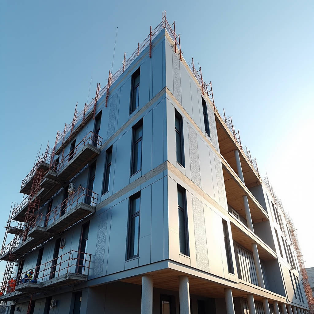
A perforated aluminum angle is frequently treated as a secondary hardware item, yet its mechanical behavior under real-world wind and seismic loads determines whether a rainscreen or a cable-support run stays aligned for decades. Most spec sheets list hole patterns and leg dimensions, but they rarely explain how those perforations reduce the section's effective net area, how that reduction shifts the bending capacity, and why the same profile behaves differently in a curtain wall bracket than in an overhead tray. This article walks through the load-path logic, the coating and alloy decisions that matter, and the fabrication tolerances that separate a reliable component from a field headache. The goal is to give engineers and procurement teams a practical checklist they can apply before approving a purchase order, not a marketing summary.
Why Perforations Change the Structural Story
A solid angle leg carries load across its full cross-section. Punch a row of holes through that leg and the remaining material must carry the same force through a smaller area. The ratio of net section to gross section is the governing efficiency factor, and it is rarely constant across a product line. A profile with 12 mm holes on 25 mm centres loses far more capacity than one with 8 mm holes on 40 mm centres, even though both are sold under the same generic name.
For a single angle used as a bracing leg or a light support, the practical effect is straightforward. The bending stress rises in proportion to the loss of net section, so a design that assumes gross-section values will be optimistic by roughly the same percentage as the hole area. Engineers who skip this correction end up with brackets that flex visibly under load, fasteners that loosen from micro-movement, and callbacks that are expensive to fix on a finished facade.
Net Section and the Load Path
The correct approach is to calculate the net section at the critical hole row, then apply the same allowable stress used for the gross section. For a leg of thickness t and width b with a hole of diameter d, the net area is approximately (b - d) × t. When the hole is staggered, the governing section is the one that removes the most area along any single path. This is the same logic found in the AISC steel construction manual, adapted for aluminum's lower modulus and its different allowable stress tables.
For wind-loaded conditions, the Aluminum Association's Aluminum Design Manual (ADM) provides allowable stress values that already account for the reduced ductility of heat-treated alloys. A 6061-T6 angle, for example, has a yield strength near 240 MPa, but the allowable bending stress is far lower once safety factors and buckling checks are applied. Using the net section with those allowable values gives a defensible design. Ignoring the holes and using gross values does not.
Alloy and Temper: Not All Perforated Angles Are Equal
The most common alloys in this product category are 6061-T6 and 6063-T5. Both are extruded, but they serve different purposes. 6061-T6 offers higher strength and is the standard choice for structural bracing and load-bearing brackets. 6063-T5 is softer, easier to form, and often used for architectural trim and light framing where the finish matters more than the load.
Perforation is usually done after extrusion, either by punching or by drilling. Punching is faster and cheaper, but it leaves a slight burr and work-hardens the edge of the hole. Drilling is cleaner but slower and more expensive. For a structural application, the burr matters because it creates a stress concentration that can initiate a crack under cyclic wind loading. A quick pass with a deburring tool or a vibratory finishing step removes the risk at a negligible cost per part.
| Alloy / Temper | Yield Strength (MPa) | Typical Use | Weldability | Corrosion Resistance |
|---|---|---|---|---|
| 6061-T6 | ~240 | Structural brackets, bracing, load-bearing frames | Fair, requires careful filler selection | Good, anodizes well |
| 6063-T5 | ~145 | Architectural trim, light framing, cable runs | Good for general work | Good, excellent for anodizing |
| 6060-T5 | ~130 | Decorative profiles, low-load trim | Good | Good |
For exterior use, the protective finish is as important as the alloy. A bare 6061-T6 angle will develop a dull oxide layer that is harmless structurally but looks poor on an exposed facade. A clear anodize (typically 10 to 20 microns per the AA standards) protects the surface and preserves the metal's appearance. A PVDF or powder coating adds color and a thicker barrier, but it also adds cost and must be applied to a properly pretreated surface or it will fail by peeling.
Coating Selection for Exterior Lifespan
When the angle is visible on a building, the coating choice determines how long it stays presentable. An unpainted anodized finish is the most durable for a bare-metal look and is specified under the AAMA 611 standard for anodized aluminum. For a painted finish, a 70% PVDF (polyvinylidene fluoride) resin coating applied to a two-coat or three-coat system meets the AAMA 2605 specification, which is the benchmark for high-performance exterior coatings.
For a component that is hidden inside a cavity or behind a rainscreen panel, the coating is less critical, but it is still wise to avoid bare aluminum in contact with dissimilar metals. Galvanic corrosion occurs when aluminum touches steel or copper in the presence of moisture. The remedy is a barrier, either a paint film, an anodized layer, or a nylon or rubber isolation gasket at the contact point. This is a standard detail in any curtain wall manual and is often overlooked in the rush to order fasteners.
Futeng® supplies perforated aluminum angle profiles in both 6061-T6 and 6063-T5 with a range of finishes, and their fabrication team routinely deburrs punched holes before shipping. For procurement teams that need a dependable source for facade brackets and tray supports, that attention to edge quality is a practical differentiator that shows up in lower field rejection rates.
Fabrication Tolerances and Hole Geometry
The pitch, diameter, and stagger of the perforations are not decorative. They are set by the manufacturer to suit a specific fastener or a specific mounting pattern. Before ordering, confirm three numbers: the hole diameter, the centre-to-centre pitch, and the edge distance from the hole to the leg edge. A hole punched too close to the edge will tear out under load, turning a simple bracket into a safety issue.
Typical perforated aluminum angle from a reputable mill holds a hole diameter tolerance of ±0.3 mm and a pitch tolerance of ±0.5 mm over a 3 m length. Leg width and thickness follow the extrusion tolerance in the Aluminum Association's standards, usually ±0.4 mm on thickness for a 3 mm leg. These numbers matter because a bracket that is 1 mm off in hole position will not line up with the pre-drilled holes in a curtain wall mullion, forcing the installer to re-drill on site.
Re-drilling on a finished, coated profile destroys the coating at the hole and exposes bare metal to corrosion. It also voids the warranty on the coating in most cases. The cheapest way to avoid this is to demand a tolerance report with every batch and to spot-check incoming material with a simple caliper and a hole gauge. A ten-minute inspection saves a day of rework on the scaffold.
Wind Load and Seismic Considerations
For a facade bracket, the governing load is usually wind suction on the panel, which can be several kilopascals on a tall building. The bracket transfers that load into the structure through the perforated angle. The design must check both the net section of the angle and the bearing stress where the fastener bears against the hole edge. Bearing stress is the load divided by the projected area of the hole, and it is often the limiting factor when holes are small and loads are high.
For seismic zones, the additional consideration is ductility. Heat-treated 6061-T6 has limited ductility, so a bracket that must yield and absorb energy during an earthquake should be designed conservatively, with a higher safety factor than a static wind load would require. The FEMA and ASCE 7 guidance on nonstructural components provides the loading combinations, and the ADM provides the allowable stresses. Combining the two gives a bracket that survives both a storm and a seismic event without a brittle failure at a hole edge.
For cable tray and conduit support runs, the loads are simpler but the failure mode is the same. A tray full of heavy cables can pull a bracket out of alignment if the perforated angle is undersized. The standard practice is to size the angle so that the deflection at the free end stays below L/200, which keeps the tray level and prevents cables from sliding. This is a quick calculation that any engineer can do with the net section and the alloy's modulus of 69 GPa.
Standards and References Worth Keeping
Three documents anchor most of the engineering decisions in this area. The Aluminum Association's Aluminum Design Manual sets the allowable stress framework for structural aluminum. The AAMA 2605 specification governs high-performance organic coatings on exterior aluminum. The ASTM B221 standard covers aluminum and aluminum-alloy extruded bars, rods, wires, profiles, and tubes, and it is the reference for dimensional tolerance and alloy verification.
For fastener and bearing design, the guidance in the AISC manual, adapted for aluminum, is a practical starting point. The key difference is that aluminum's lower modulus means deflection, not stress, often controls the design. A bracket that passes a stress check may still deflect too much for a tight joint, so always check deflection as well as stress.
Practical Procurement Checklist
- Confirm the alloy and temper, and request a mill certificate for each batch.
- Verify hole diameter, pitch, and edge distance against your fastener and mounting pattern.
- Request a tolerance report for leg width, thickness, and hole position.
- Specify the coating system (anodize, PVDF, or powder) and the applicable AAMA standard.
- Check for burrs on punched holes and require deburring for structural parts.
- Confirm galvanic isolation details if the angle contacts steel or copper.
- Run a net-section and deflection check before approving the order.
Most field failures with perforated aluminum angle trace back to a missing detail, not to a catastrophic design error. A hole too close to the edge, a coating that was not specified, a batch that drifted out of tolerance, a galvanic contact left unprotected. Each of these is preventable with a few minutes of review at the specification stage.
For a facade or a plant, the takeaway is the same. Treat the perforated aluminum angle as a structural component with a defined net section, a defined coating, and a defined tolerance envelope. Confirm those three things against your drawing, and the bracket will do its job for the life of the building. Skip them, and you are betting the alignment of a finished wall on the assumption that every hole in every batch is exactly where the catalog says it should be.