Perforated Aluminium Screens Engineering Guide for Open Area Wind Load and Coating Durability
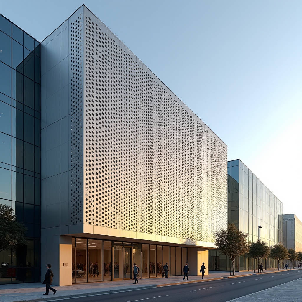
Perforated aluminium screens occupy a distinct position in contemporary facade engineering, sitting between a fully opaque rainscreen and an open mesh. The engineering value of these panels is not decorative whimsy; it is the controlled management of three forces at once — solar gain, wind pressure, and acoustic transmission. For a solid aluminium cladding specialist supplying 2.0 to 3.0 mm plate to global contractors, the practical question is how to specify, fabricate, and fix perforated aluminium screens without compromising the structural integrity that a solid sheet guarantees. This article walks through the load paths, open-area calculations, coating behaviour, and installation economics that determine whether a perforated screen performs for thirty years or fails in five. The focus stays on engineering numbers, not marketing language.
Why Open Area Governs Every Decision
The single most influential parameter in any perforated aluminium screen is the open area ratio — the percentage of the panel that is void. It drives structural stiffness, wind load transfer, visual transparency, and acoustic absorption simultaneously. A 40% open area screen behaves structurally like a much thinner plate, because the remaining ligament between holes carries the full load. The European standard EN 1991-1-4 and the American ASCE 7 both treat perforated screens as partially permeable elements, which means the net pressure coefficient differs from a solid panel. Architects who specify a perforated screen purely for aesthetics often overlook that the perforation pattern converts a pressure-driven cladding into a combination of pressure and suction on individual ligaments.
Calculating Effective Thickness
For a 3.0 mm aluminium plate with a 40% open area, the effective load-bearing section is roughly equivalent to a 1.8 mm solid sheet in bending. This is not a guess; it follows from the reduction in the second moment of area across the perforated zone. Contractors should ask their fabricator for a stiffness calculation, not just a panel weight. A common failure mode is specifying a perforated screen with the same fixing spacing as a solid panel, then discovering excessive deflection under wind load. The fix is either reducing the open area, increasing plate thickness, or shortening the support span.
The Perforation Patterns That Matter
Round holes in a staggered (60-degree) pattern are the industry default because they offer the best balance of strength and open area. Square and slotted patterns push open area higher but create stress concentrations at the corners. For facade work, the practical range is 3 mm to 25 mm hole diameters with open areas between 20% and 50%. Above 50%, the panel loses enough stiffness that it must be treated as a mesh rather than a plate, which changes the entire fixing strategy.
| Pattern | Typical Hole Ø (mm) | Open Area (%) | Relative Stiffness | Typical Use |
|---|---|---|---|---|
| Round, staggered | 3–12 | 20–40 | High | Facade screens, sunshades |
| Round, straight | 5–15 | 25–40 | Medium | Acoustic panels |
| Square | 6–20 | 35–50 | Medium-low | Decorative partitions |
| Slotted | 3×20 | 40–55 | Low | Ventilation, plant screens |
Wind Load and the Perforation Factor
Wind engineering treats perforated aluminium screens as elements that allow pressure equalisation. When the open area exceeds roughly 30%, the internal pressure partially cancels the external suction, which can actually reduce net load on the panel. However, this benefit disappears when the screen is backed by a solid wall with a small cavity. The perforation factor in EN 1991-1-4, Table 7.10, gives guidance on how to adjust net pressure coefficients based on the ratio of open area to gross area. A competent facade engineer will run this calculation before committing to a hole pattern, because the difference between a 30% and a 45% open area can change the required fixing strength by 20% or more.
Fixing and Substructure
Perforated screens are almost always fixed to a steel or aluminium subframe with concealed brackets. The critical detail is that the bracket must bear on the solid ligament between holes, never on a void. Edge distance from the hole to the fixing point should be at least two hole diameters. For a 3.0 mm plate, self-tapping screws or rivets through the perforated zone are acceptable only if the fastener engages a solid backing rail. Where the screen spans large openings, stiffening ribs welded to the rear face restore the bending capacity lost to perforation.
Coating Durability on Perforated Surfaces
The coating system matters more on a perforated screen than on a solid panel, because the cut edges of the holes expose bare aluminium to the atmosphere. A standard PVDF (polyvinylidene fluoride) finish at 25–30 microns dry film thickness is the baseline for exterior facade use, conforming to AAMA 2605 for the highest durability class. The perforation process must be done before coating, and the coating must fully cover the hole walls. Edge coverage on the hole perimeter is a frequent failure point, showing up as white oxide bloom within three to five years on cheap powder-coated screens. Powder coating at 60–80 microns can be adequate, but it must be specified with a proper pretreatment (chromate or chrome-free) to survive coastal environments.
For coastal or industrial exposures, specify a 2-coat PVDF system at 25 microns minimum and require the fabricator to demonstrate edge coverage on the perforation walls through a cross-section micrograph. This single check prevents most premature corrosion claims.
Comparing Coating Options
| Coating System | Dry Film Thickness | Standard | Salt Spray Resistance | Typical Warranty |
|---|---|---|---|---|
| PVDF 2-coat | 25–30 µm | AAMA 2605 | 4000 h minimum | 20–30 years |
| PVDF 3-coat | 30–35 µm | AAMA 2605 | 4000 h minimum | 25–30 years |
| Polyester powder | 60–80 µm | Qualicoat Class 2 | 1000 h | 10–15 years |
| Anodised (Class 25) | 25 µm oxide | ISO 7599 | Moderate | 15–20 years |
Acoustic Performance
A perforated aluminium screen with a backing cavity and a sound-absorbing infill (mineral wool or acoustic foam) becomes a resonant absorber. The peak absorption frequency depends on hole diameter, open area, and cavity depth. For a 30% open area panel with a 100 mm cavity, the absorption band typically centres around 500–1000 Hz, which is useful for highway noise barriers and plant enclosures. The same screen without infill provides negligible absorption and functions only as a reflective barrier. Contractors specifying screens for acoustic reasons must order the complete assembly — panel, infill, and cavity — as one engineered system, not as separate components.
Installation Economics
Perforated screens cost more per square metre than equivalent solid panels for three reasons: the punching operation adds a fabrication step, the coating of cut edges requires extra process control, and the handling of lighter, more flexible panels demands more care on site. On a typical facade project, the installed cost premium for a 40% open perforated screen over a solid 3.0 mm PVDF panel is roughly 15–25%. The premium is offset by reduced dead load on the structure, lower solar heat gain through the envelope, and the elimination of separate sunshade systems.
Cost Drivers at a Glance
| Cost Component | Solid Panel | Perforated Screen (40% OA) |
|---|---|---|
| Raw plate (3.0 mm) | Baseline | Same |
| Punching/fabrication | Baseline | +8–12% |
| Coating & edge control | Baseline | +5–8% |
| Handling & fixing | Baseline | +2–5% |
| Net installed cost | Baseline | +15–25% |
Fire and Thermal Behaviour
Solid aluminium plate is non-combustible, and perforation does not change that classification. The open area can actually improve fire behaviour by allowing heat and smoke to vent, but it also reduces the panel's resistance to localised melting if a fire burns directly against it. Aluminium melts around 660°C, so perforated screens should never be relied upon as a primary fire barrier. For facade applications where fire spread is a concern, the perforation pattern must be coordinated with the cavity fire-stopping strategy, and the screen should be treated as a decorative or solar-control layer, not a fire-resisting element. Reference BS 8414 for facade fire testing methodology.
Specification Checklist for Procurement
When a procurement manager receives a perforated screen enquiry, the following items must be confirmed in writing before quotation. First, the open area ratio and hole pattern, because they drive both cost and wind load. Second, the coating system and the required standard, with edge coverage verified. Third, the fixing spacing and the substructure design, because the panel alone is not the load path. Fourth, the acoustic requirement, if any, which dictates the infill and cavity depth. Fifth, the tolerance on hole placement — a perforated screen with inconsistent hole spacing is visually unacceptable at close range, so specify a positional tolerance of ±0.5 mm.
Fabricators with dedicated perforation and coating lines, such as those supplying solid aluminium cladding panels under the Futeng® brand, can hold these tolerances reliably at production scale. The value of a supplier is measured not in the raw sheet price but in the consistency of the punched pattern, the integrity of the coated hole walls, and the accuracy of the flatness after perforation. A panel that bows or cups after punching will never lie flat on the facade, regardless of how good the coating is.
Practical Engineering Guidance
The most reliable way to specify a perforated aluminium screen is to treat it as a structural element with a defined load path, not as a decorative sheet. Confirm the open area, run the wind pressure calculation with the perforation factor, verify the coating edge coverage, and require the fabricator to supply a flatness and stiffness statement. For spans above 1.2 metres, add rear stiffening or reduce the open area. For coastal sites, insist on AAMA 2605 PVDF with verified edge coverage. For acoustic duty, buy the complete assembly with infill and cavity as one system. These decisions, made at the specification stage, determine whether the screen delivers thirty years of controlled solar, wind, and acoustic performance or becomes a maintenance liability within a decade.