Perforated Aluminium Facade Engineering Open Area Wind Load and Acoustic Design
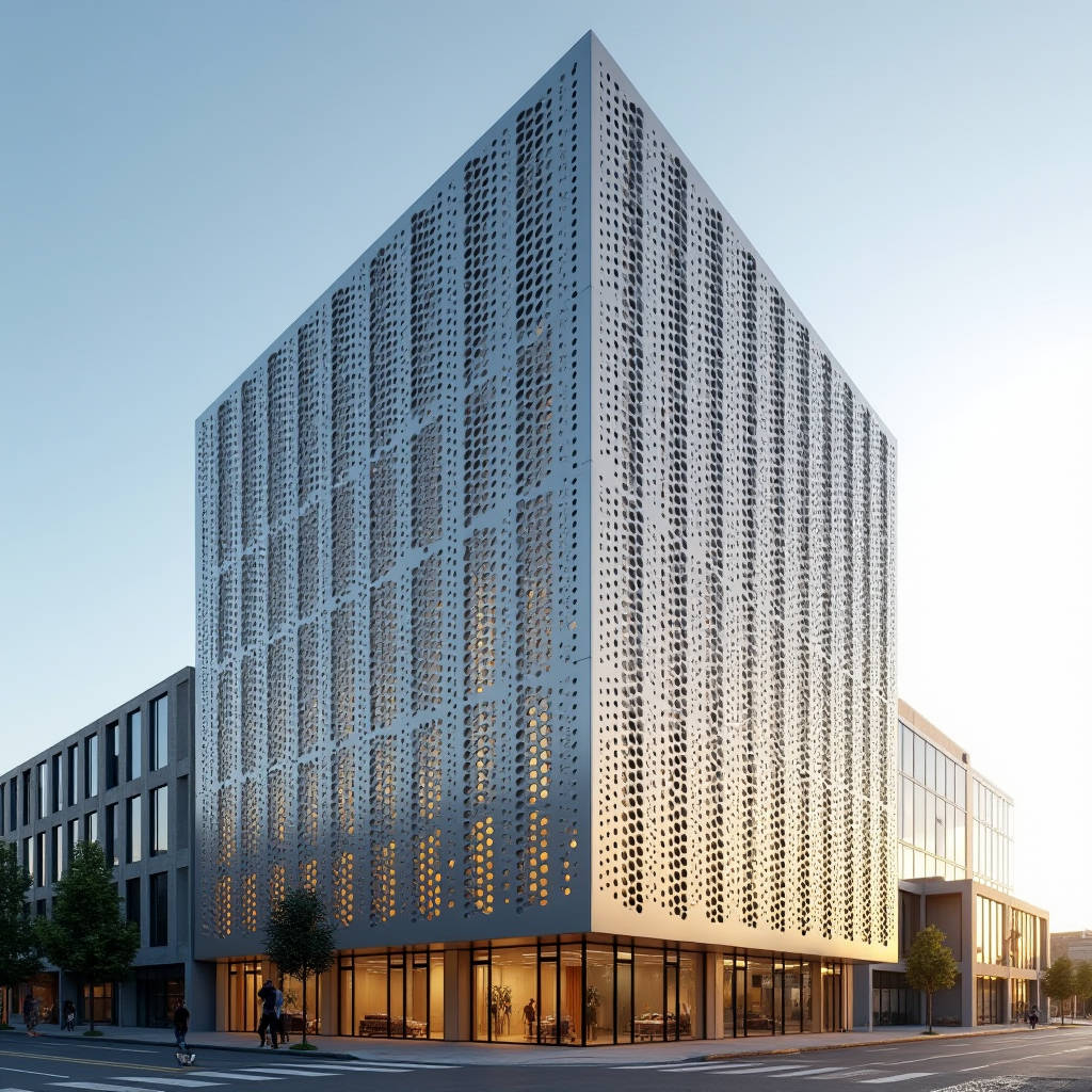
Perforated aluminium has moved far beyond its reputation as a decorative skin. On large commercial facades it is now a structural and environmental component, yet most specification documents still treat it as a purely aesthetic choice. The real engineering begins with the open area ratio, the hole geometry, and the way those two variables interact with wind load, solar gain, and acoustic performance. This article walks through the technical decisions that determine whether a perforated aluminium rainscreen performs for twenty years or fails within five. We focus on solid aluminium sheet, not composite panels, because the substrate thickness and edge detailing are what govern long-term flatness and corrosion resistance. By the end you will have the calculation framework and the specification checklist needed to take a perforated aluminium facade from concept to a compliant, buildable system.
Why Open Area Ratio Controls Everything
The open area ratio is the percentage of the sheet surface removed by the perforations. It is the single most influential parameter on a perforated aluminium facade because it drives structural, thermal, and acoustic behaviour simultaneously. A 40 percent open area panel carries roughly 40 percent less material stiffness in the perforated zone, which changes the deflection under wind suction. It also changes the pressure equalisation inside the cavity, which in turn alters the design wind load the substructure must resist.
For a vented rainscreen, the rule of thumb is that an open area above 25 percent begins to compromise the pressure-equalisation benefit of the cavity. Below 15 percent, the panel behaves closer to a solid sheet and the ventilation benefit drops sharply. The useful engineering band for most commercial facades sits between 15 and 30 percent open area. Within that band, the perforation pattern and the hole diameter determine whether the panel acts as a wind screen, a solar shade, or an acoustic absorber.
Hole Geometry and Staggering
Round holes in a staggered (60-degree) pattern are the industry default because they offer the best structural retention per unit of open area. Square and slotted perforations remove more material along straight lines, which creates weak bands that can buckle under repeated thermal cycling. If the design calls for square holes, the panel thickness should be increased by at least one gauge to restore stiffness. The stagger pattern also matters for light transmission: a straight-line pattern creates visible bright bands across the facade, while a staggered layout diffuses light more evenly.
Wind Load and Structural Design
Perforated panels experience lower net wind pressure than solid panels because air passes through the openings, but the reduction is not linear with open area. The net pressure coefficient depends on the porosity, the cavity depth, and the building's corner zones. A common specification error is to assume a 30 percent open panel carries 30 percent less load. In practice, the reduction in design pressure is often only 10 to 20 percent because the remaining solid portions still capture the full pressure gradient.
For high-rise facades, the corner and parapet zones demand the most attention. These areas see the highest local suction pressures, and a thin perforated sheet can flutter or fatigue at the fixing points. The recommended minimum thickness for a perforated aluminium rainscreen panel is 2.0 mm for panels under 1.5 square metres, and 3.0 mm for larger panels or those in wind zones above 40 metres in height. Fixings should be placed at a maximum of 300 mm centres along the perimeter, with additional fixings at the panel corners.
Deflection Limits
Perforated panels are more flexible than solid sheets of the same thickness, so the deflection limit must be checked against the perforated section properties, not the gross sheet thickness. A practical limit is L/60 for the visible bow under wind load, with a tighter L/120 if the panel sits adjacent to a glazed opening. When the open area exceeds 25 percent, consider adding a stiffening edge trim or a hidden rib to hold the panel flat.
Solar Performance and Natural Ventilation
Perforated aluminium is one of the most effective passive solar shading devices available, provided the open area and the mounting offset are specified together. The shade coefficient of a perforated panel depends on the open area, the panel colour, and the depth of the cavity behind it. A dark-coloured panel with 30 percent open area can cut direct solar gain on the glazing behind it by 40 to 50 percent, while still allowing daylight through. A light-coloured panel reflects more radiation but transmits more diffuse light, which can create glare in office interiors.
The cavity depth is the variable most often overlooked. For a perforated screen to ventilate the cavity and exhaust hot air, the offset from the substrate should be at least 60 mm, and ideally 80 to 100 mm. This depth allows the buoyancy-driven airflow to carry heat away from the building envelope. A cavity that is too shallow converts the perforated panel into a stagnant thermal trap, which raises the temperature of the substrate and accelerates the ageing of the insulation behind it.
Acoustic Performance
Perforated aluminium panels function as acoustic absorbers when backed by an air cavity and a sound-absorbing layer such as mineral wool. The absorption coefficient peaks at a frequency determined by the hole diameter, the panel thickness, and the cavity depth. For a typical round-hole pattern with 5 mm holes on a 2.0 mm sheet and a 50 mm cavity, the peak absorption sits in the 500 to 1000 Hz range, which covers speech and traffic noise. This makes perforated aluminium a practical choice for acoustic screens on transport corridors and for sound-attenuating facades near airports.
If the acoustic requirement is the primary driver, specify the perforation pattern and cavity depth together as a tuned system rather than selecting a decorative pattern first. A supplier should provide the absorption coefficient curve for the exact panel build, not a generic value. The backing layer must be moisture-resistant and non-combustible to meet the fire performance requirements of the facade assembly.
Coating and Corrosion Protection
The perforation process exposes fresh aluminium edges that are more vulnerable to corrosion than the factory-coated face. The coating system must therefore be specified for edge protection, not just colour. A two-coat PVDF system with a fluoropolymer topcoat of 25 to 30 microns and a corrosion-inhibiting primer is the minimum for coastal or industrial environments. For aggressive marine exposures, specify a three-coat system with a thicker primer and a clear anodic barrier on the cut edges.
Perforated panels also trap moisture inside the holes, so the drainage and weep paths in the substructure must be designed to release water rather than hold it. The fixing holes should be sealed with a compatible gasket or sealant, and the panel edges should be returned or hemmed to remove sharp cut edges that can initiate pitting. A well-detailed perforated aluminium facade in a PVDF finish will outlast a poorly detailed solid panel, because the perforations allow the cavity to dry out instead of trapping condensation.
Coating Performance Comparison
| Coating System | Total Film Thickness | Salt Spray Resistance | UV Fade Resistance | Typical Lifespan |
|---|---|---|---|---|
| Two-coat PVDF | 30–35 microns | 1000+ hours | Excellent | 20–25 years |
| Three-coat PVDF | 40–45 microns | 1500+ hours | Excellent | 25–30 years |
| Polyester | 25 microns | 500–800 hours | Good | 10–15 years |
| Anodised (Class 1) | 18–25 microns oxide | High, edge-sensitive | Very good | 20+ years |
Film thickness figures align with the guidance in AAMA 2605 for fluoropolymer coatings on architectural aluminium. For perforated panels, the salt spray result matters more than for solid sheets because the cut edges are exposed on every hole.
Manufacturing Tolerances and Flatness
Perforating a sheet removes material and releases residual stress, which can cause the panel to bow or oil-can after fabrication. The control of flatness starts with the alloy and the temper. A 5000-series alloy in a stable temper holds flatness better than a 3000-series alloy after perforation. The punching process itself must use a controlled feed rate and a sharp die to avoid burrs on the hole edges, which not only look poor but also create stress raisers that can crack under thermal cycling.
For panels larger than 2.4 metres, specify a flatness tolerance of 3 mm over a 1.5 metre straight edge and require a deburring or edge-rolling pass on the perforated holes. The standard sheet sizes before folding are typically 1220 by 2440 mm, but custom panel sizes are common on large projects. When a panel is folded into a cassette or tray profile, the perforation must stop short of the fold line to avoid weakening the bend. A minimum of 15 mm of solid material at the fold line is a safe specification.
Installation and Substructure
The substructure for a perforated aluminium rainscreen is the same concealed bracket and rail system used for solid panels, but the bracket spacing must account for the reduced panel stiffness. On a solid 2.0 mm panel, a vertical rail at 600 mm centres is common. On a perforated panel with 25 percent open area, reduce the rail spacing to 500 mm or increase the panel thickness to maintain the same deflection performance.
Pressure equalisation is the key difference in installation. The perforations allow air and water vapour to move freely into the cavity, so the cavity must be vented at the base and the head to prevent the build-up of positive pressure behind the panel. The insulation layer must be a closed-cell or faced product that does not absorb moisture from the ventilated cavity. The fire performance of the whole assembly must be verified as a system, because the open panel changes the fire behaviour compared with a sealed rainscreen.
Specification Checklist
- Confirm the open area ratio and the perforation pattern with the structural engineer before freezing the design.
- Select the panel thickness from the deflection check on the perforated section, not the gross sheet.
- Specify a three-coat PVDF system for coastal or industrial sites, with a documented salt spray test.
- Set the cavity depth between 60 and 100 mm to preserve ventilation and solar shading performance.
- Require the supplier to provide the acoustic absorption curve for the exact panel build.
- Stop the perforation a minimum of 15 mm from any fold line.
- Verify the fire performance of the complete assembly, including the backing and insulation.
- Confirm the flatness tolerance and deburring requirement in the fabrication specification.
Cost Reality
Perforated aluminium costs more per square metre than a plain solid panel because the perforation adds a processing step and the material yield is lower. The premium typically runs 15 to 30 percent over a solid panel of the same thickness and finish, depending on the hole density and the pattern complexity. That premium is offset by the savings in the glazing system, because a well-designed perforated screen can reduce the solar control glazing specification and the associated HVAC load. On a large office tower, the reduction in cooling plant capacity can recover the perforation premium within the first few years of operation.
For procurement teams, the practical advice is to budget for the perforation premium and the tighter substructure spacing, and to request a sample panel for every new pattern. A sample reveals the flatness, the edge quality, and the light transmission far more reliably than a rendered image. On complex or high-volume projects, a reliable supplier such as Futeng® can provide the perforation patterns, the coating system, and the panel fabrication in one controlled production line, which shortens lead times and keeps the tolerances consistent across the whole facade.
Closing Engineering Advice
The success of a perforated aluminium facade depends on decisions made in the first two weeks of design, not in the factory. Lock the open area ratio, the panel thickness, the cavity depth, and the coating system before the architectural detail is frozen. Then verify the deflection, the pressure equalisation, and the acoustic behaviour against the actual panel build. A perforated aluminium facade that is specified as a complete system, with the structural and environmental parameters treated as interdependent, will deliver the visual drama, the solar control, and the service life that the design intends. Treat the perforation as an engineering variable, and the panel will perform as a structural and environmental component rather than a decorative afterthought.