Engineering Perforated Aluminum Panels for Wind Load Open Area and Coating Performance
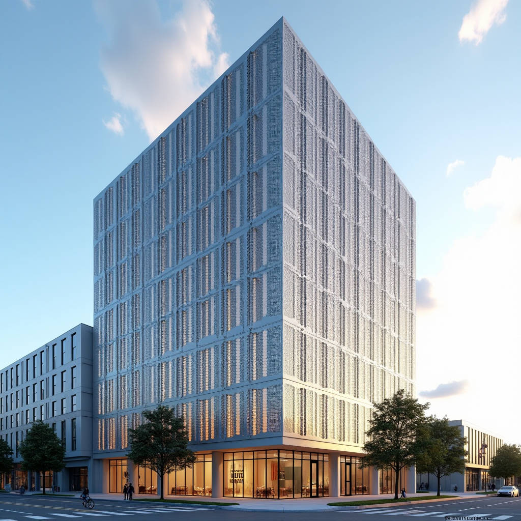
Perforated aluminum panels have moved from a niche architectural accent to a load-bearing cladding strategy that directly affects structural budgets, thermal performance, and maintenance cycles. For facade contractors and procurement teams, the real question is not whether perforation looks good, but how open area, hole geometry, and alloy temper change wind load coefficients, acoustic absorption, and PVDF warranty coverage. This article walks through the engineering decisions behind specifying perforated aluminum panels for high-rise and industrial facades, with hard numbers on open area ratios, plate thickness, and coating performance. You will leave with a practical checklist for vetting supplier drawings, calculating effective wind loads, and avoiding the most common specification errors that surface only at the fabrication stage.
Why Perforation Changes More Than Appearance
When an architect specifies perforated aluminum panels, the design intent is usually daylight diffusion, natural ventilation, or solar shading. But the perforation pattern also alters the panel's structural stiffness, its effective surface area for coating adhesion, and its behavior under wind suction. A solid 3.0 mm aluminum sheet with a 40% open area loses a measurable portion of its bending stiffness, so the backup framing and the panel gauge must be re-evaluated together, not treated as independent decisions.
For a typical 2.5 mm 5052-H32 panel with a 60 mm hole diameter and 50% open area, the effective flexural rigidity drops by roughly 25% compared with the same panel unperforated. That figure matters when a facade engineer runs a wind load calculation for a 40-storey tower in a coastal zone. The perforation turns a solid plate into an orthotropic structure, and the load path changes accordingly. Contractors who carry the same backup steel schedule from a solid-panel project into a perforated one often end up with excessive deflection between supports.
Open Area Ratio and Wind Load Coefficients
Open area is the single most important parameter in perforated panel engineering. It is defined as the ratio of hole area to total panel area, expressed as a percentage. Standard patterns range from 10% to 60%, with 40% to 50% being common for sunscreens and ventilation screens. The open area directly influences the net wind pressure coefficient because perforated panels allow airflow through the facade, which reduces the pressure differential across the panel surface.
Published wind tunnel data for perforated screens show that the net pressure coefficient drops as open area increases. At roughly 40% open area, the net wind load on a perforated screen can be 40% to 60% lower than on a solid panel of the same dimensions, depending on the surrounding building geometry and the porosity of adjacent elements. This is why perforated panels are frequently specified for high wind zones where a solid panel would demand heavier framing. The trade-off is that the remaining solid land area still carries the full load, so the engineer must calculate the load on the solid struts between holes, not simply scale down the total load.
For procurement teams, this means the open area ratio must be stated on the shop drawing with a tolerance, typically ±2%. A supplier that silently shifts from a 45% to a 50% open area to reduce material weight changes the structural assumptions and the acoustic performance at the same time. Verify the pattern against the approved mock-up before production begins.
Hole Geometry, Stagger, and Pattern Limits
Hole shape and arrangement are not purely aesthetic. Round holes in a staggered (60-degree) pattern are the most common because they provide the highest open area for a given hole spacing and the best structural stability between adjacent holes. Square and slotted holes are used for specific airflow or visual effects but create stress concentrations at the corners that can propagate cracks under thermal cycling.
A practical rule for round holes is that the minimum land area between holes should be no less than one hole diameter. For a 60 mm hole, the center-to-center spacing should be at least 120 mm. When spacing drops below this, the panel loses stiffness and the perforation tooling wears unevenly, producing burrs that compromise the PVDF coating. Burr control is a real quality issue: a raised burr on the hole edge creates a thin coating film that fails first in salt-spray testing.
The minimum hole diameter is also constrained by the sheet thickness. For 2.0 mm aluminum, holes below 6 mm are difficult to punch cleanly without excessive tool wear. For 3.0 mm plate, the practical minimum rises to about 8 mm. If the design calls for fine micro-perforation below these limits, the panel must be laser-cut or the gauge reduced, both of which change cost and lead time.
Alloy and Temper Selection
The alloy choice for perforated aluminum panels should follow the same logic as for solid cladding, with one extra consideration: the perforation process work-hardens the material at the hole edges. The industry standard alloys are 3003, 5052, and 6061. For architectural facades, 5052-H32 is the most common because it offers a good balance of corrosion resistance, formability, and strength after punching.
5052-H32 provides a typical yield strength around 193 MPa and tensile strength around 228 MPa. For coastal and industrial environments, this alloy resists pitting better than 3003. The H32 temper indicates strain-hardened and stabilized, which is the correct starting point for a panel that will be punched and then formed. Specifying a fully annealed 0-temper sheet for perforation is a mistake because the punched edges remain soft and the panel can creep under sustained wind load.
For very large spans or high wind zones, 6061-T6 offers higher strength (yield around 276 MPa) but is less formable and more prone to cracking at the hole edges if the punch clearance is not controlled. Most facade suppliers default to 5052-H32 for perforated work, and that is a defensible default for most projects. The material certificate should state the alloy, temper, and thickness, and the coil or sheet lot should be traceable to the mill.
Coating Systems and Perforation Edge Coverage
The PVDF coating is what protects the aluminum from corrosion, and perforation complicates coating coverage because the hole edges are exposed. A two-coat or three-coat PVDF system with a nominal dry film thickness of 25 to 30 microns is standard for exterior cladding. The coating is applied after perforation, so the hole edges receive full coverage, but the coating thickness at the sharp edge is thinner than on the flat face.
This is where the coating supplier's warranty language matters. Most PVDF warranties cover the flat panel surface but exclude edges and cut edges. For perforated panels, the hole edges are effectively cut edges, so the warranty exclusion can be significant. In practice, a well-controlled perforation process with minimal burrs, followed by proper cleaning and pretreatment, produces hole edges that perform well in salt-spray testing. The ASTM B117 salt-spray test and the AAMA 2605 specification for high-performance organic coatings are the relevant references for verifying performance.
For coastal projects, specify a three-coat PVDF system with a corrosion-inhibiting primer and verify the minimum film thickness at the hole edges using a coating thickness gauge on a sacrificial sample. The AAMA 2605 standard is the benchmark for the highest exterior performance class, and it should be stated in the specification rather than left to the supplier's discretion.
| Coating System | Nominal DFT (microns) | Relevant Standard | Typical Warranty | Best Fit |
|---|---|---|---|---|
| Two-coat PVDF (70% resin) | 25 | AAMA 2604 | 10 years | Interior, mild climate |
| Three-coat PVDF (70% resin) | 30 | AAMA 2605 | 20 years | Coastal, high UV |
| Polyester | 20 | Not for exterior | 5 years | Interior screens |
| Anodized (Class I) | 18-25 micron film | AAMA 611 | 10-15 years | Industrial, matte finish |
Acoustic Performance and Ventilation
Perforated aluminum panels are frequently specified for acoustic screens and equipment enclosures because the open area allows sound to pass through to an absorptive backing. The sound absorption coefficient depends on the open area, hole diameter, panel thickness, and the air cavity behind the panel. A perforated panel with 40% open area and a 50 mm cavity behind it can achieve a noise reduction coefficient of 0.6 to 0.8 when backed with a sound-absorbing core.
For ventilation, the open area must be balanced against the structural and coating constraints. A facade that relies on perforated panels for natural ventilation needs a clear statement of the required airflow rate, which translates into a minimum open area. The engineer should verify that the open area specified for aesthetics is sufficient for the ventilation requirement, and that the hole pattern does not create whistling at certain wind speeds. Whistling is a real field complaint that is difficult to fix after installation, so a mock-up test in a wind tunnel or a careful review of the hole geometry is worthwhile for large projects.
Fabrication Tolerances and Quality Control
Perforation introduces dimensional tolerances that are tighter than for solid panels. The hole diameter, center-to-center spacing, and the overall pattern registration must be controlled to avoid a visible mismatch between adjacent panels. A common tolerance is ±0.5 mm on hole diameter and ±1 mm on hole spacing. The panel flatness after perforation is also affected because the punching process can introduce local distortion, especially at high open areas.
For a 2.5 mm 5052 panel with 50% open area, the flatness tolerance after perforation is typically 3 mm over a 1.5 m span. If the panel is to be installed in a highly reflective finish, even this tolerance can produce visible waviness, so the finish choice and flatness tolerance should be coordinated. A matte or stipple finish hides minor distortion better than a mirror finish.
Quality control should include a first-article inspection on the perforation pattern, a coating thickness check at the hole edges, and a flatness check on a sample panel. The supplier should provide a material certificate for the aluminum alloy and a coating certificate from the paint manufacturer. These documents are the basis for the warranty claim if a problem surfaces later.
Cost Drivers and Budget Planning
Perforation adds cost to a solid aluminum panel, and the cost scales with open area and hole density. A 40% open area pattern typically adds 15% to 25% to the panel cost compared with the same solid panel, because the punching operation, tooling, and additional quality control are charged separately. Higher open areas above 50% add more because the tooling wears faster and the rejection rate rises.
The hole size also affects cost. Smaller holes require more punches per square meter and more tooling, so a micro-perforated pattern can double the panel cost. For budget planning, request a per-square-meter price for the exact pattern, not a generic perforated panel price. The framing and installation cost are also higher for perforated panels because the backup structure must be designed for the reduced stiffness, and the installers must handle the panels carefully to avoid denting the thin land areas between holes.
For a typical 2.5 mm 5052 panel with 40% round-hole open area and a three-coat PVDF finish, a reasonable budget estimate for the fabricated panel is in the range of USD 45 to 65 per square meter, depending on volume and finish. This excludes the framing, installation, and engineering. For large-volume facade packages, suppliers such as Futeng® can provide factory-direct pricing with consistent tooling and coating quality, which is worth confirming early in the budget cycle.
Specification Checklist for Procurement
Before you issue a purchase order for perforated aluminum panels, verify that the shop drawing and the specification include the following items. Missing any one of these can lead to a rejected delivery or a field failure.
- Alloy and temper: 5052-H32 or 6061-T6, stated on the material certificate.
- Thickness: 2.0, 2.5, or 3.0 mm, with tolerance.
- Open area ratio: stated with a ±2% tolerance.
- Hole diameter, shape, and stagger pattern, referenced to the approved mock-up.
- Coating system: three-coat PVDF per AAMA 2605 for exterior, with minimum DFT.
- Flatness tolerance and finish type (matte vs. reflective).
- Wind load calculation basis, including the net pressure coefficient used.
- Acoustic or ventilation requirement, if applicable.
Field Installation Considerations
Installation of perforated panels requires care that solid panels do not. The thin land areas between holes are vulnerable to denting from tools and ladders, so protective film should remain on the panels until the last possible moment. The backup framing must be aligned precisely because perforation makes any misalignment visible through the pattern. Thermal expansion is also a consideration: the perforated panel has a lower effective stiffness, so the expansion joints between panels must be sized correctly to prevent buckling.
For high-rise work, the panels are often installed with a rainscreen system that allows pressure equalization behind the facade. The perforation changes the pressure equalization behavior, so the cavity depth and the venting strategy must be reviewed with the facade engineer. A panel that is too porous can allow water to enter the cavity, so the drainage and flashing details need to account for the higher airflow through the facade.
Final Engineering Guidance
Perforated aluminum panels reward a disciplined specification process. Start with the open area ratio and hole geometry, verify the alloy and coating against the environment, and confirm the wind load and acoustic assumptions with the facade engineer before fabrication. The extra effort at the specification stage prevents the most expensive problems, which appear only after the panels are on the building and the perforation pattern is impossible to change. Treat the perforated panel as a structural element, not a decorative skin, and the project will perform as designed.