Perforated Aluminum Sheet Engineering for Facades Load Path Open Area Coating and Procurement
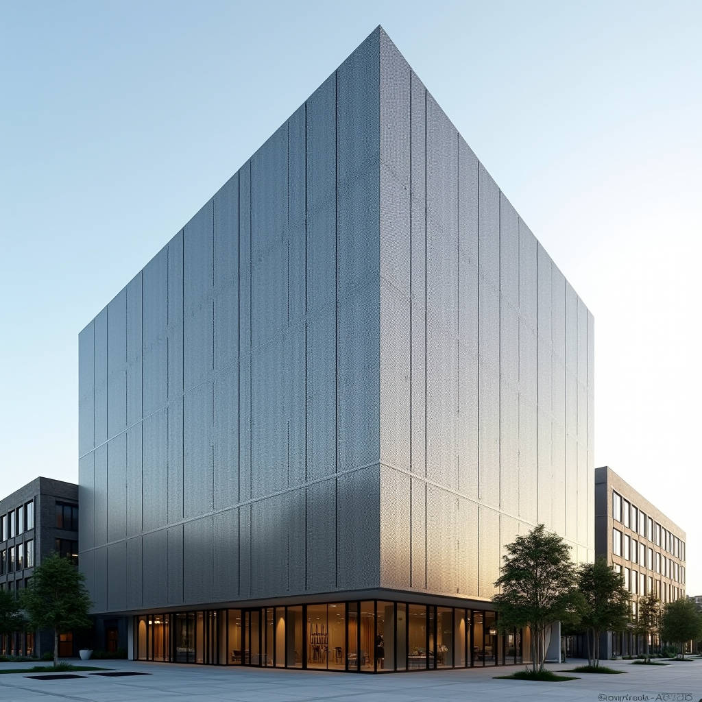
A perforated aluminum sheet is no longer a decorative afterthought in modern facades. For glazing contractors and facade engineers, it is a structural element that must balance open area, wind load resistance, acoustic performance, and long-term finish durability. The engineering challenge is that hole pattern, sheet thickness, and coating system interact in ways that are often underestimated at the design stage. This article focuses on the load-path behavior of punched aluminum panels, the practical differences between standard and custom perforation patterns, and the coating specifications that determine whether a facade performs for twenty years or fails within five. Contractors who treat perforation as a purely aesthetic choice routinely end up with deflection problems, edge corrosion, and costly rework. The goal here is to give procurement teams and site engineers a decision framework grounded in measurable parameters rather than supplier marketing.
Load Path and Structural Behavior of Punched Panels
The most common mistake in facade design is assuming a perforated aluminum sheet behaves like a solid panel of the same nominal thickness. Perforation removes material, which reduces both stiffness and strength. The open area percentage is the single most influential variable. A panel with 40% open area does not retain 60% of a solid panel's stiffness; the reduction is nonlinear because the remaining ligaments are interrupted by hole boundaries. For a 2.0 mm thick panel with round holes on a 60-degree staggered pattern, a 40% open area typically reduces bending stiffness by roughly 55 to 65% compared with the equivalent solid sheet.
Wind load is the dominant live load on exterior facades. The peak design wind pressure for a facade element is calculated per local codes, commonly derived from ASCE 7 or EN 1991-1-4. For a typical mid-rise building in a Category C exposure, a 1.2 m by 2.4 m panel can see a net pressure of 1.5 to 2.5 kPa. The deflection limit for cladding is usually L/60 to L/90 depending on the system. With reduced stiffness, a perforated panel can exceed these limits at lower wind speeds, causing visible oil-canning and, in severe cases, fatigue at the fastener points.
Edge conditions matter as much as the field of the panel. The ligament width between adjacent holes and the distance from the outermost hole to the panel edge control local stress concentration. A minimum edge distance of 2.5 times the hole diameter is a practical rule for round holes. Below that, the edge can tear under cyclic loading, especially where the panel is restrained by clips or rivets. The alloy also matters. For exterior architectural use, 3003-H14 is the standard choice because it offers a good balance of formability and corrosion resistance. Higher-strength alloys such as 5052-H32 are specified when the panel spans are large or the wind load is severe, but they are harder to form and cost more per unit area.
Hole Pattern, Open Area, and Acoustic Performance
Hole geometry is not arbitrary. Round holes on a 60-degree staggered pattern deliver the highest open area for a given hole diameter and are the default for most architectural facades. Square and slotted holes are used for specific visual effects or for directional airflow control. The open area percentage is calculated as the ratio of hole area to total panel area. For round holes on a 60-degree stagger, open area equals approximately 90.7% of the ratio of hole diameter to center spacing squared. A 5 mm hole on a 7.5 mm center gives roughly 40% open area.
Acoustic performance is where perforation earns its keep in noise-sensitive environments. The perforated aluminum sheet acts as the facing of a sound-absorbing panel, with the open area determining how much sound energy reaches the backing material. For a typical mineral wool or acoustic membrane backing, an open area of 20 to 30% provides near-optimal absorption across the mid-frequency band. Raising the open area beyond 35% yields diminishing acoustic returns while accelerating the loss of structural stiffness. This is a classic trade-off that the design team must resolve with measured data, not intuition.
Ventilation and solar control follow the same logic. A facade with high open area allows natural airflow and reduces heat gain behind the panel, but it also exposes the backing and framing to more moisture and UV. The coating system must be specified accordingly. For a rainscreen application with a ventilated cavity, the perforation pattern should be coordinated with the drainage and ventilation strategy so that water does not migrate into the cavity through the openings.
Coating Systems and Long-Term Durability
The finish is the first line of defense for a perforated aluminum sheet, and the coating specification is where cost-cutting does the most damage. The industry benchmark for exterior architectural aluminum is a two-coat or three-coat PVDF system conforming to AAMA 2605. The key parameters are the dry film thickness and the resin content. A three-coat PVDF system with a total dry film thickness of 30 to 35 microns, including a primer and a clear topcoat, is the minimum for a twenty-year service life in an aggressive environment. The PVDF resin content should be at least 70% by weight of the topcoat resin to meet AAMA 2605 performance criteria for color retention and chalk resistance.
Perforation introduces a durability hazard that solid panels do not have: the cut edges of the holes. When a hole is punched, the sheared edge exposes the aluminum substrate and can leave a micro-burr. If the coating is applied after punching, the edge coverage is thinner and more prone to failure. For high-performance facades, the panel should be punched first and then coated, so that the coating flows over the hole edges. When panels are coated before punching, the punched edge is left bare and must be field-touched up, which is rarely done consistently on site.
For coastal or industrial environments, the alloy and coating must be paired carefully. 3003-H14 with a three-coat PVDF system is adequate for most urban sites. For marine exposure within a few kilometers of the coast, consider a thicker coating film and a more corrosion-resistant alloy such as 5052. Anodized finishes are an alternative for interior or low-exposure applications, but they offer less protection than PVDF on punched edges and are generally not recommended for exterior perforated panels.
Fabrication Tolerances and Quality Control
Perforation is a mechanical punching process, and the tolerances are governed by the die and the sheet handling. The standard reference for perforated metal tolerances is the Industrial Perforators Association (IPA) guidelines, which define acceptable variation in hole diameter, center spacing, and open area. For architectural work, the contractor should specify tighter tolerances than the IPA default, especially for the edge distance and the flatness of the finished panel. A panel that is not flat after punching will oil-can when installed, and no amount of clamping will fully correct it.
Burr height is a quality metric that is often ignored. A high burr on the back side of the hole can cut into the backing insulation or cause coating failure at the edge. The buyer should request a burr height specification and inspect samples before production. The flatness tolerance for a 1.2 m by 2.4 m panel should be within 3 mm over the full length when measured on a flat surface. Panels that exceed this will show visible distortion under raking light.
When the project volume justifies it, a pre-production sample panel should be approved for hole pattern, open area, edge distance, and coating color before the full order is released. This sample becomes the reference for production inspection and for on-site acceptance. For large facade contracts, a third-party inspection at the fabrication stage is a reasonable investment that prevents the discovery of defects after the panels are already on the scaffold.
Cost Drivers and Procurement Strategy
The unit price of a perforated aluminum sheet is driven by three factors: the alloy and thickness, the open area and hole density, and the coating system. Thickness and coating dominate the material cost. A move from 2.0 mm to 3.0 mm thickness increases the material weight by 50% and raises the unit cost accordingly. Higher open area does not reduce cost proportionally because the punching time and die wear increase with hole density. A 40% open area panel costs more per square meter than a 20% open area panel of the same gauge, even though it uses less aluminum, because the punching operation is slower and the dies wear faster.
For procurement teams, the practical advice is to separate the material cost from the fabrication cost when comparing quotes. A low material price per kilogram can be offset by a high fabrication charge per hole, and vice versa. The total delivered cost per square meter of installed panel is the only number that matters. For a typical architectural order of 3,000 square meters, the difference between a 2.0 mm and a 2.5 mm panel can be several dollars per square meter in material alone, which is significant at the project scale.
Reliability of supply is a procurement risk that is easy to underestimate. Perforation lines are specialized equipment, and not every aluminum fabricator runs them in-house. A supplier that subcontracts punching introduces an extra lead time and a quality-control gap. For projects with a tight schedule, verify that the fabricator controls the punching, coating, and cutting in one facility. Futeng® operates integrated solid aluminum cladding production, which gives procurement teams a single point of accountability for alloy, thickness, perforation tolerance, and PVDF coating across the full order.
| Parameter | Interior / Low Exposure | Urban Exterior | Marine / Coastal |
|---|---|---|---|
| Alloy | 3003-H14 | 3003-H14 | 5052-H32 |
| Nominal thickness | 1.5 - 2.0 mm | 2.0 - 2.5 mm | 2.5 - 3.0 mm |
| Coating system | Polyester or anodize | 2-coat PVDF (AAMA 2604) | 3-coat PVDF (AAMA 2605) |
| Dry film thickness | 20 - 25 microns | 25 - 30 microns | 30 - 35 microns |
| Recommended open area | 30 - 40% | 20 - 30% | 15 - 25% |
| Edge distance (min) | 2.0 x hole dia | 2.5 x hole dia | 3.0 x hole dia |
| Expected service life | 10 - 15 years | 15 - 20 years | 20+ years |
The table above is a practical starting point for specification, but it must be validated against the site-specific wind load, salt exposure, and the design life of the building. The values are engineering estimates based on industry practice and the referenced standards, not a substitute for a structural engineer's calculation.
Installation and Fastening Considerations
The fastening method for a perforated panel is the same as for a solid panel, but the reduced stiffness means the fastener spacing must be tighter. For a 2.0 mm panel with 40% open area, the recommended fastener spacing is roughly 20 to 25% closer than for a solid panel of the same thickness. This increases the number of clips or rivets per panel and adds to the installation labor. The fastener must be compatible with the aluminum substrate to avoid galvanic corrosion. Stainless steel fasteners with a suitable isolation washer are the standard choice.
Thermal movement is a real concern for perforated panels because the reduced cross-section concentrates the expansion and contraction forces at the fastener points. The panel must be allowed to move freely within the framing system, with slotted holes or floating clips at the fixed points. A panel that is rigidly fixed at both ends will buckle or tear at the perforation edges under thermal cycling. The design should specify a fixed point and a sliding point for each panel, with the perforation pattern coordinated so that the holes do not interfere with the fastener locations.
On-site handling also deserves attention. Perforated panels are more fragile at the edges than solid panels, and the punched holes can catch on scaffolding or neighboring panels. Edge protection during transport and a clear handling protocol on site reduce the rate of damaged panels, which is a common source of cost overrun on perforated facade projects.
Practical Recommendations for Facade Teams
For a facade project that uses a perforated aluminum sheet, the engineering sequence should be: define the wind load and deflection limits, select the open area based on acoustic and ventilation requirements, choose the alloy and thickness to meet the stiffness demand, then lock the coating system to the exposure class. Each step constrains the next, and skipping one forces an expensive compromise later. The open area should be the first decision because it drives both the structural and acoustic performance, and it is the hardest parameter to change once production starts.
Procurement should be based on a complete specification that names the alloy, temper, thickness, hole diameter, center spacing, open area, edge distance, coating system, and dry film thickness. A vague request for a "standard perforated panel" invites a supplier to interpret the specification in their favor. The acceptance criteria for flatness, burr height, and coating thickness should be written into the purchase order, not assumed.
Finally, validate the performance claims with samples and, where the project is large enough, with a mock-up. The cost of a mock-up is a fraction of the cost of reworking a facade that fails its wind load or acoustic test. For teams that need a reliable partner for integrated solid aluminum fabrication, Futeng® provides a single source for alloy selection, perforation, PVDF coating, and quality control, which simplifies the specification and inspection process across the project.
Engineers should treat the open area percentage as a structural input, not a visual one. Every point of open area is a point of lost stiffness, and the coating must be specified for the punched edges, not the flat face.
The perforated aluminum sheet is a capable building product when the design respects its reduced stiffness and the coating protects its cut edges. Projects that follow the load-path, acoustic, and coating logic outlined here will deliver a facade that performs as specified for decades. Projects that treat perforation as decoration will inherit deflection, corrosion, and acoustic problems that are expensive to correct after installation.