Perforated Aluminum Facade Engineering Open Area Ratio Alloy and Wind Load Specs for Contractors
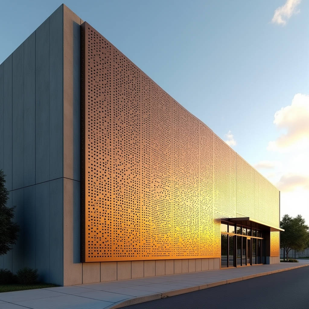
Perforated aluminum has moved far beyond decorative screens and into the load-bearing vocabulary of modern curtain wall engineering. For facade contractors and procurement teams, the real question is not whether to use it, but how to specify it so that structural performance, wind load resistance, and fabrication cost stay in balance. This article concentrates on the engineering decisions that determine whether a perforated aluminum facade performs for twenty years or fails after two. We examine open area ratios, hole patterns, alloy selection, coating systems, and the panel-to-substructure connection details that separate a sound project from a costly rework. The goal is practical: give specifiers and buyers a clear method for evaluating perforated aluminum panels before they commit to a budget.
Why Perforated Aluminum Demands a Different Engineering Mindset
Solid aluminum cladding carries load through a continuous membrane. Perforated aluminum interrupts that membrane, so every hole becomes a stress concentration point. The same 2.0 mm sheet that easily resists 1.5 kPa of wind load as a solid panel may deflect noticeably once you remove 30 to 50 percent of its material. Contractors who treat perforated panels like solid ones often discover this the hard way, after a section buckles or the fasteners loosen.
The engineering approach shifts in three ways. First, the effective section modulus drops, so you must either increase sheet thickness or add stiffening ribs. Second, edge conditions change because the perforation zone stops short of the folded flanges. Third, the open area directly affects the pressure differential across the panel, which changes how wind load transmits to the substructure. None of these are reasons to avoid the material. They are reasons to specify it with data, not guesswork.
Open Area Ratio and Its Structural Cost
The open area ratio is the single most important number on a perforated aluminum drawing. It is the percentage of the sheet surface removed by holes. Common architectural ranges sit between 20 and 50 percent. At 40 percent open area, a 2.0 mm sheet behaves structurally closer to a 1.2 mm solid sheet in terms of stiffness, yet it still weighs the same as the original 2.0 mm material.
This has a direct consequence for cost. You are paying for the full 2.0 mm sheet but only getting the stiffness of a thinner equivalent. The practical fix is to order a heavier gauge than you would for a solid panel of the same span, or to add a stiffening frame behind the perforated face. For a typical 1200 mm by 2400 mm panel spanning between vertical mullions, a 40 percent open area pattern usually requires either 2.5 mm material or a perimeter box frame to hold deflection within the L/180 limit many facade specs demand.
Specify the open area ratio on the drawing, not just the hole size. Two panels with identical 8 mm holes can behave completely differently if one has a 30 percent open area and the other 45 percent.
Hole Pattern, Stagger, and Material Strength
Hole geometry determines both the visual character and the residual strength of the sheet. Staggered patterns distribute holes more evenly and leave wider ligament bridges between holes, which improves residual strength compared to straight-line patterns of the same open area. Round holes are the most common because they create the least stress concentration at the ligament. Square, slotted, and custom shapes are possible but each sharp corner becomes a crack initiation point under repeated thermal cycling.
The minimum ligament width between adjacent holes is the controlling dimension. For architectural panels, a ligament of at least 1.5 times the sheet thickness is a sound working rule. Below that, the web between holes becomes too thin to carry the local bending stress, and the panel may tear during the folding or punching operation. Fabricators with CNC punching equipment can hold tight tolerances, but the design must respect the material limits from the start.
Alloy Selection for Perforated Facade Panels
Not every aluminum alloy punches the same way. The three alloys that dominate architectural perforated panels are 3003, 5052, and 6061. Each has a different balance of formability, strength, and corrosion resistance, and the choice should follow the panel geometry and the coastal or industrial environment of the project.
| Alloy | Temper | Yield Strength (MPa) | Formability | Corrosion Resistance | Best Use |
|---|---|---|---|---|---|
| 3003 | H14 | ~145 | Excellent | Good | Large flat panels, deep folds, interior screens |
| 5052 | H32 | ~193 | Very good | Excellent | Coastal facades, high wind zones |
| 6061 | T6 | ~276 | Fair | Good | Structural frames, stiffened panels, high load areas |
For a typical curtain wall panel that needs to be punched and folded without cracking, 3003-H14 is the workhorse. When the project sits within a few kilometers of salt water, 5052-H32 offers better pitting resistance with only a modest reduction in formability. 6061-T6 is stiffer but harder to punch cleanly at high open areas, so it appears more often in the supporting frame than in the perforated face itself. A reliable supplier such as Futeng® can source all three alloys and advise on the correct temper for a given hole pattern.
Coating Systems and Long-Term Weathering
The perforation process exposes fresh aluminum at every hole edge, so the coating system must cover the cut surfaces or the panel will corrode from the inside out. Two coating families dominate architectural aluminum: PVDF (polyvinylidene fluoride) and powder coating. They are not interchangeable in performance or price.
| Coating | Typical Film Thickness | UV Resistance | Chalking / Fading | Salt Spray Resistance | Typical Warranty Range |
|---|---|---|---|---|---|
| PVDF (70/30) | 25–30 µm | Excellent | Minimal | Very high | 20–25 years |
| Powder (polyester) | 60–80 µm | Good | Moderate | Moderate | 10–15 years |
| Anodized | 15–25 µm | Excellent | Minimal | High | 15–25 years |
For exterior perforated facades, PVDF remains the reference standard because its resin chemistry resists the UV-driven chalking that turns a dark panel chalky white within a few years. The coating is applied after perforation and folding, so the hole edges receive full coverage. Powder coating is a viable budget option for interior screens or sheltered applications, but its thicker film does not compensate for weaker UV resistance. AAMA 2605 is the specification that defines the highest exterior durability class for PVDF on aluminum, and any serious facade project should require it.
Wind Load and Pressure Equalization
Because perforated panels are not airtight, the wind load calculation differs from a solid cladding system. The open area allows air to pass through, which reduces the net pressure on the panel but shifts the load to the structure behind it. The design must account for both the external wind pressure and the internal pressure that develops in the cavity between the perforated panel and the building envelope.
A practical approach is to treat the perforated panel as a rainscreen with a pressure-equalized cavity. The perforation itself provides the ventilation that keeps the cavity dry and equalizes pressure, which actually improves the durability of the insulation and the substructure behind it. The wind load on the perforated panel is then calculated as a fraction of the full external pressure, using the solidity ratio of the pattern. For a 40 percent open area, the panel sees roughly 60 percent of the free-field pressure, but the mullions and brackets must still be designed for the full load because the wind does not stop at the panel face.
Reference the wind load provisions in ASCE 7 and the aluminum design rules in the Aluminum Association's Aluminum Design Manual when sizing the substructure. These documents give the pressure coefficients and allowable stress limits that keep the assembly within safe deflection and fatigue margins.
Panel-to-Substructure Connections
The connection detail is where perforated facades most often fail. Screws and rivets must land on solid ligament material, not on a hole. This means the fastener pattern on the drawing must be coordinated with the hole grid, which is a common source of field errors. The cleanest solution is to specify a solid margin band around the perimeter of the panel, typically 30 to 50 mm wide, where no holes are punched. This band carries the fasteners and the folded flanges, keeping the perforation away from the stress-critical edge.
For large panels, hidden clip systems or a continuous aluminum subframe behind the perforated face reduce visible fasteners and spread the load more evenly. The subframe also adds the stiffness that a high open area removes from the face sheet. When the panel is folded into a tray section, the folded flanges add rigidity along the edges, so the combination of a perimeter flange and a perimeter solid band is the most efficient way to recover lost stiffness without jumping to a heavier gauge.
Always request a shop drawing that overlays the fastener positions on the hole grid. If a fastener lands within one ligament of a hole, the detail is wrong and will loosen in service.
Fabrication Tolerances and Quality Control
Perforated panels require tighter fabrication control than solid panels because the holes magnify any deviation. Hole pitch, hole diameter, and sheet flatness all affect how the panel fits the substructure and how the pattern reads across a large facade. A pattern that drifts by 1 mm across a 2400 mm panel becomes visibly misaligned at the joints between adjacent panels.
Set acceptance tolerances in the specification: hole diameter within ±0.15 mm, hole pitch within ±0.3 mm, and panel flatness within 2 mm over a 1200 mm span. Require a first-article inspection on the first production panel before the full run begins. This single step catches tooling wear and programming errors before they repeat across hundreds of panels. ISO 9001 certification on the fabrication shop is a reasonable baseline, and the punching equipment should be CNC-controlled to hold the pattern repeatably.
Cost Drivers and Budget Planning
Perforated aluminum costs more than solid cladding of the same gauge, and the premium comes from three sources: the punching operation, the heavier gauge required to recover stiffness, and the coating of the cut edges. A 40 percent open area panel in 2.5 mm 5052 with PVDF coating typically costs 25 to 40 percent more per square meter than a solid 2.0 mm PVDF panel. The exact figure depends on hole size, pattern complexity, and the fabricator's tooling.
To control cost without sacrificing performance, standardize the hole pattern across the project rather than using a different pattern on every elevation. Custom patterns require dedicated tooling and slower punch cycles. A single round-hole pattern at a fixed stagger keeps punching fast and the tooling cost low. Order panels in standard sizes where possible, and let the fabricator cut to final dimensions rather than asking for odd custom sizes that waste material.
Specification Checklist for Facade Buyers
Before you issue a request for quotation on a perforated aluminum facade, confirm that your specification covers these points. Missing any one of them invites a dispute or a field failure later.
- Open area ratio stated as a percentage with a tolerance, not just a hole size.
- Alloy and temper matched to the environment and the panel geometry.
- Minimum ligament width between holes, tied to sheet thickness.
- Solid perimeter band width for fastener placement.
- Coating system and film thickness, with AAMA 2605 for exterior PVDF.
- Wind load calculation method and pressure-equalized cavity design.
- Fabrication tolerances for hole pitch, diameter, and flatness.
- First-article inspection requirement before full production.
Perforated aluminum is a capable and durable facade material when the engineering is done with the same rigor as a solid panel. The open area is a design asset that controls solar heat gain, diffuses light, and creates architectural depth, but it is also a structural liability that must be priced and engineered honestly. Specify the open area, the alloy, the coating, and the connection detail on the drawing, and the panel will perform as intended. A supplier with deep fabrication experience, such as Futeng®, can help you match the pattern and gauge to the wind load and budget of your specific project, turning a risky detail into a predictable one.